주의 : 이 글은 완성된 회로가 아닌 완성되다 만 회로를 다루고 있습니다.
I. 서론
'닌텐도(Nintendo)'라는 회사, 또는 그 회사의 게임기에 대해 들어본 적이 있는가? 이 회사는 일본에서 유래한 화투(はなふだ, 花札 , 花鬪)와 같은 유흥을 위한 제품 및 장난감을 만드는 회사로, 대한민국에서 '닌텐도 DS Lite' 라는 제품을 흥행시켜 수많은 한국인들에게 닌텐도 화투 이후로 닌텐도라는 이름을 다시 알렸다.(지금은 'Nintendo Switch'가 또다시 닌텐도라는 이름을 알리고 있다.) 내가 초등학교 1~2학년 때쯤, 친한 친구가 닌텐도 DS Lite를 구매해서 나에게 보여주었을 때 나는 이런 신기한 기계가 존재한다는 사실이 흥미로웠다. 이후 명절에 사촌들이 할아버지집에 놀러 왔을 때 닌텐도 DS Lite를 가져와서 즐겁게 게임하는 모습을 구경할 수 있었고, 가끔씩 닌텐도 DS Lite를 빌려달라고 요청해서 시간 가는 줄 모르고 즐겼던 기억이 있다.

그러던 어느 날, 부모님이 수학경시대회(조선일보 또는 두산동아가 주최했던 걸로 기억한다.)에서 100점 만점 중 90점을 넘겨야 얻을 수 있는 금메달을 따면 닌텐도 DS Lite를 사주겠다고 말씀하셨다.(내가 졸랐던 건지, 아니면 부모님이 먼저 제안한 건지는 기억이 잘 나지 않는다, 그러나 높은 확률로 내가 졸랐을 거라 생각한다.) 평소에 동메달이나 은메달을 따왔던 나는 까짓 거 한 번 해보자고 생각해서 열심히 공부했고, 신기하게도 금메달에 해당하는 점수를 얻게 되어 금메달과 닌텐도 DS Lite를 동시에 가질 수 있었다.(화투를 쳐본 사람이라면 쉽게 짐작할 수 있겠지만, 닌텐도를 살 때부터 내 인생은 쾌락 또는 나락으로 기울기 시작했다.) 부모님께서는 내가 닌텐도 DS Lite를 동생과 함께 공부하는 데 사용하라며 '두뇌 트레이닝'과 '닌텐독스'라는 게임 칩을 사주셨다. 그러나 닌텐도 회사의 제품은 공부하기 위한 용도로 개발된 것이 아니라 유흥을 위해 개발되었기에, 친구들은 '포켓몬스터 DP'나 '별의 커비 도팡일당의 습격'과 같은 도파민이 팡팡 터지는 유혹적인 게임 칩을 주로 사용하였다. 나는 그들이 쾌락에 빠져 즐겁게 게임을 즐기는 모습이 부러웠지만, 그것보다 친구들과 같이 모여 이야기할 관심사가 생겼다는 사실이 더 기뻤다.

시간이 흘러 명절이 다가왔고, 사촌들이 할아버지 집에 놀러 왔었다. 신기하게도 사촌들 중 한 명이 'R4' 칩을 사용하여 수많은 게임들을 하나의 칩에서 실행시키는 모습을 볼 수 있었다. 나는 이 사실이 매우 놀라웠고, 나도 R4 칩 하나만 구매한다면 수많은 게임들을 즐길 수 있다는 유혹에 넘어가 게임 소프트웨어 불법 복제 칩인 R4 칩을 구매하였다. 나는 인터넷을 통해 이 칩을 컴퓨터에 연결하면 새로운 게임이 나올 때마다 그 소프트웨어를 다운로드 한 뒤 R4 칩에 집어넣어서 그 게임을 플레이할 수 있다는 사실을 알게 되었고, 초등학교 시절의 대부분을 R4 칩 또는 TT칩이 장착된 닌텐도를 플레이하며 보냈다. 지금 생각해 보면 잘못된 판단이었지만 그 당시 나는 이 유용한 기능을 친구들도 즐겼으면 해서 한 게임 당 50원 내지 100원을 받고 설치해주었다.(흥미롭게도, 가격의 기준을 책정할 때 할머니가 마을회관에서 화투를 칠 때 책정했던 판돈을 참조하였다.) 거기에 더해 나는 치트 파일을 다루는 방법도 알게 되었고, R4 칩이나 TT 칩에 치트를 설치해 주거나 특정 포켓몬의 능력치 값을 조작 또는 스킬 목록을 수정하여 내가 원하는 포켓몬을 설계할 수 있었다. 이는 명백히 잘못된 행위지만 그 당시 나는 그 경계선에 대한 개념이 없어서 폭주기관차처럼 R4 칩, TT 칩, 그리고 닌텐도 DS Lite에 몰두하였다. 이 행위는 내가 새로운 컴퓨터를 사게 되고 나서 컴퓨터에 몰두하느라 소홀해졌고, 그 기회에 부모님과 동생이 내가 모르는 사이 닌텐도 DS Lite를 중고로 팔아버려 닌텐도 DS Lite를 잃어버렸다고 판단하여 완전히 잊히게 되었다.

컴퓨터는 닌텐도 DS Lite보다 더 자극적이었다. 화면도 몇 배는 더 크고 게임 종류도 수십, 수백 가지는 되었다. 특히 친구들에게 닌텐도 게임을 깔아주며 알게 된 친구들 중 한 명이 나에게 컴퓨터 게임 설치, 컴퓨터 분해 등을 의뢰하였고, 이 친구의 친구가 내게 부탁하여 하루는 그래픽 카드(GPU)를 직접 컴퓨터에 장착시켜보기도 했다. 이 과정을 거치며 나는 언젠가 커서 그래픽 카드를 만드는 사람이 되고 싶어 졌고, 인터넷을 통해 그래픽 카드 제조 회사를 검색해 보며 처음으로 엔비디아(NVIDIA)라는 회사에 대해 알게 되었다. 사실 그래픽 카드는 설계와 생산을 다른 회사에서 담당한다. 설계는 엔비디아나 AMD에서, 생산은 PALIT(Palit Microsystems Ltd.), 기가바이트(Giga-Byte Technology Co., Ltd.), 그리고 사파이어(Sapphire Technology Limited)에서 담당한다.(각각을 팹리스(Fabless)와 메뉴팩쳐러(Manufacturer)라고 부르기도 한다.) 엔비디아와 AMD는 미국 회사이고 Palit, 기가바이트, 그리고 사파이어는 대만 및 홍콩 회사였기에 그 당시 나는 국내에서 그래픽 카드와 관련된 회사에 다니는 건 불가능하다고 생각하여 이 꿈을 포기하기로 했다. 사실 RAM의 경우 삼성전자에서 제작한다는 사실을 보고 RAM 제작 회사에 가보고 싶다는 생각이 살짝 들었지만 RAM 보다는 CPU나 GPU가 더 멋있어 보였기에 일찌감치 관심이 사라졌다.

그렇게 시간이 지나 나는 고등학생이 되었고, 선생님들의 압박으로 인해 진로를 정해야 했다. 그 당시 친구들은 기계공학자가 될 거라는 말을 자주 했다. 나는 그 직업이 뭔가 멋있어 보여서 얼떨결에 기계공학자가 되기로 결정했다. 이후 나는 대입 수시 원서를 작성해야 했고, 당시 6개의 기회 중 5개를 기계공학과로, 나머지 1개는 수상하게도 사람을 엄청 많이 뽑는 과인 전자공학부로 지원하였다. 그리고 기계공학과 1개, 전자공학부 1개에 합격하였던 나는 아무 생각 없이 지원스펙이 더 높은 학교의 전공인 전자공학부에 진학하기로 결정한다. 돌이켜보면 정말 신중하지 못한 결정이었다. 그럼에도 나는 아는 게 없었기에 그 당시만 해도 충분히 합리적이고 적절한 판단이라고 생각하였다.
학교에 입학하고 나서 나는 이 학과가 무엇을 가르치는지 교수님을 통해 들어볼 수 있었고, 놀랍게도 메모리 반도체와 비메모리 반도체를 설계한다는 사실을 알게 되었다. 나는 이때까지 전자공학부에서 전기회로나 다룰 거라고 생각했으며 반도체 제품은 '기계'라고 생각했기에 기계공학과에서 다루는 분야라고 생각했다. 그 당시 나는 전자공학부 학부과정을 졸업할 즈음에 CPU나 GPU, 하다못해 RAM이라도 설계하는 방법을 배우지 않을까 하고 생각했다. 그러나 CPU나 GPU의 설계도는 들어보지도 못하였고 반도체 관련 과목은 삼성전자나 SK 하이닉스(구 LG반도체 현대전자 하이닉스)에 들어가려는 사람들이 강의를 사고 파느라 제대로 수강신청도 못해봤다.(개XX) 이 과정을 거치면서 나는 언젠가 내가 비메모리 반도체인 CPU나 GPU 설계 기술을 갖춘다면 반드시 누구에게나 이 기술을 퍼뜨리겠다고 다짐하였다. 이후 나는 대학원에 들어가 디지털 집적회로를 설계하는 방법을 알아낼 수 있었다. 따라서 오늘 우리는 디지털 집적 회로를 설계하는 방법에 대해 알아볼 것이다.
II. 본론
디지털 집적회로를 설계하는 방법을 크게 요약하자면 아래와 같다:
--------------------------------------------------------------------------------------------------------
1. RTL 설계
2. 합성
3. 레이아웃 이전 기능성 검증(RTL vs 합성)
4. DFT 삽입
5. ATPG
6. 레이아웃 설계
7. 레이아웃 이후 기능성 검증(DFT 삽입 vs 레이아웃)
--------------------------------------------------------------------------------------------------------
1. RTL 설계
RTL(Register-Transfer Level)이란 디지털 회로의 추상화, 즉 도면이나 도형 등으로 표현한 그림을 실제 레지스터의 전달 흐름, 즉 구체적인 레지스터 셀 또는 블럭의 연결로 표현한 수준을 의미한다. 레고 블럭을 사용해서 커다란 배를 만든다고 가정해 보자. 이때 추상화는 연필로 대충 그린 배 그림이며 RTL은 레고 블럭 하나하나가 다 명시된 조립 설명서라고 이해할 수 있다. 따라서 상상 속의 회로를 실제로 구현하려면, 즉 조립하려면 어떤 블럭이 어디에 들어가야 할지를 고려하여 조립 설명서, 즉 RTL로 기술할 필요가 있다.
RTL 설계를 크게 요약하자면 아래와 같다:
--------------------------------------------------------------------------------------------------------
1) 모듈 설계 - 도면
2) 모듈 설계 - HDL
3) 테스트벤치 설계 - 도면
4) 테스트벤치 설계 - HDL
--------------------------------------------------------------------------------------------------------
RTL 설계의 경우 크게 모듈 설계와 테스트벤치 설계로 구분된다. 모듈 설계의 경우 실제 모듈에 들어가야 할 레지스터, 와이어를 기술하는 과정이며 테스트벤치 설계의 경우 설계한 모듈을 인스턴시에이션, 즉 인스턴스로 찍어내서 입력 포트 값을 바꿔가며 정상작동하는지 테스트하는 과정이다. 다양한 모듈과 테스트벤치를 설계할 수 있지만 이 글에서는 이미 잘 만들어진 TI(Texas Instruments)의 MSP430를 오픈소스로 구현한 openMSP430의 모듈과 테스트벤치를 주로 다루려 한다. 이 과정에서 나는 아래 링크의 도움을 많이 받았다:
(https://opencores.org/projects/openmsp430)
1) 모듈 설계 - 도면
도면을 그리는 방법은 노트에 연필(또는 샤프)로 그리는 방법, 윈도우 그림판, Adobe Illustrator, Inkscape 등 다양한 방법이 있지만 이 글에서는 밑그림의 경우 노트에 연필로, 최종 도면의 경우 오픈소스 프로그램인 Inkscape를 사용하려 한다. Inkscape 설치 방법은 아래의 링크를 통해 확인할 수 있다:
(https://zehonyi21.tistory.com/36)
우선 밑그림을 그려야 한다. 노트에 샤프로 간단하게 인풋 포트, 모듈(서브모듈 포함), 아웃풋 포트가 명시되어 있는 그림을 그릴 수 있다:

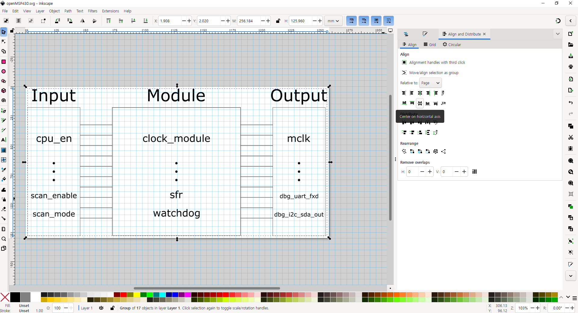
이 그림을 통해 알 수 있듯이 openMSP430모듈은 인풋 포트로 cpu_en, ... , scan_enable, scan_mode를, 서브모듈로 clock_module, ... , watchdog를, 아웃풋 포트로 mclk, ... , dbg_i2c_sda_out을 가진다는 사실을 확인할 수 있다.
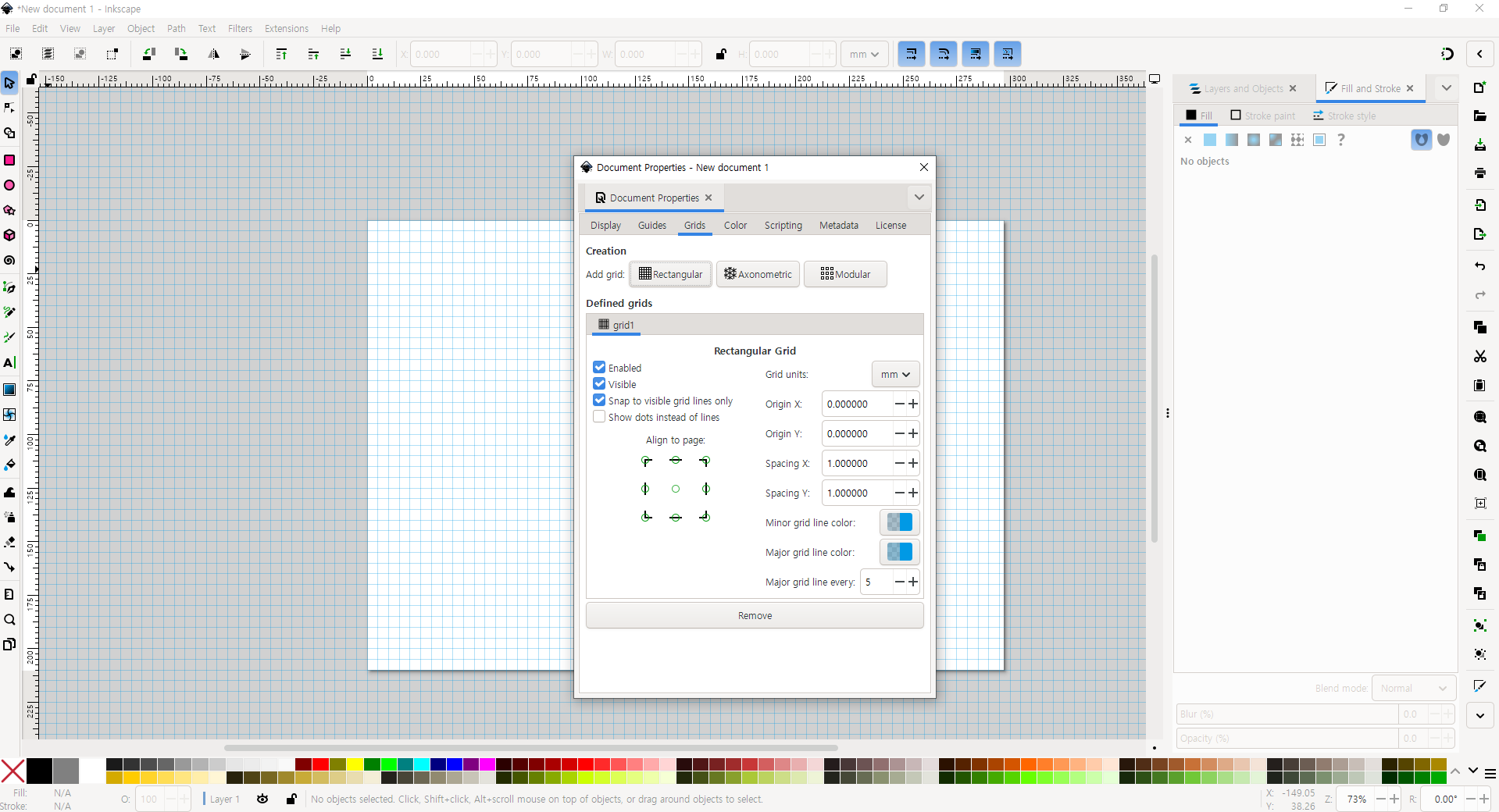
이제 최종 도면을 작성해야 한다. Inkscape를 실행시킨 뒤, 빈 페이지 기준 좌측 상단의 'File' - 'Document Properties' 를 누른다. 이후 Display 탭에서 Format을 A4로, Orientation을 가로로(Width=297) 설정한다. 그리고 나서 Grid 탭으로 간 다음 'Add Grid'의 버튼들 중 Rectangular을 클릭한다.
이후 좌측의 도형들 중 'Rectangle Tool'을 선택한 다음 밑그림과 비슷하게 사각형을 추가한다.
다음으로 좌측의 'Eliipse/Arc Tool'로 '...' 표현을, 'Pen Tool'으로 직선을, 'Text Tool'로 글자를 입력한다. 'Pen Tool'의 경우 2 점을 찍고 나서 Enter 키를 누르면 직선 및 곡선이 결정되며 'Text Tool'의 경우 글자를 적은 뒤 'Stroke Paint'를 없애고 'Fill'을 활성화해야 두껍지 않은 글씨를 얻을 수 있다.

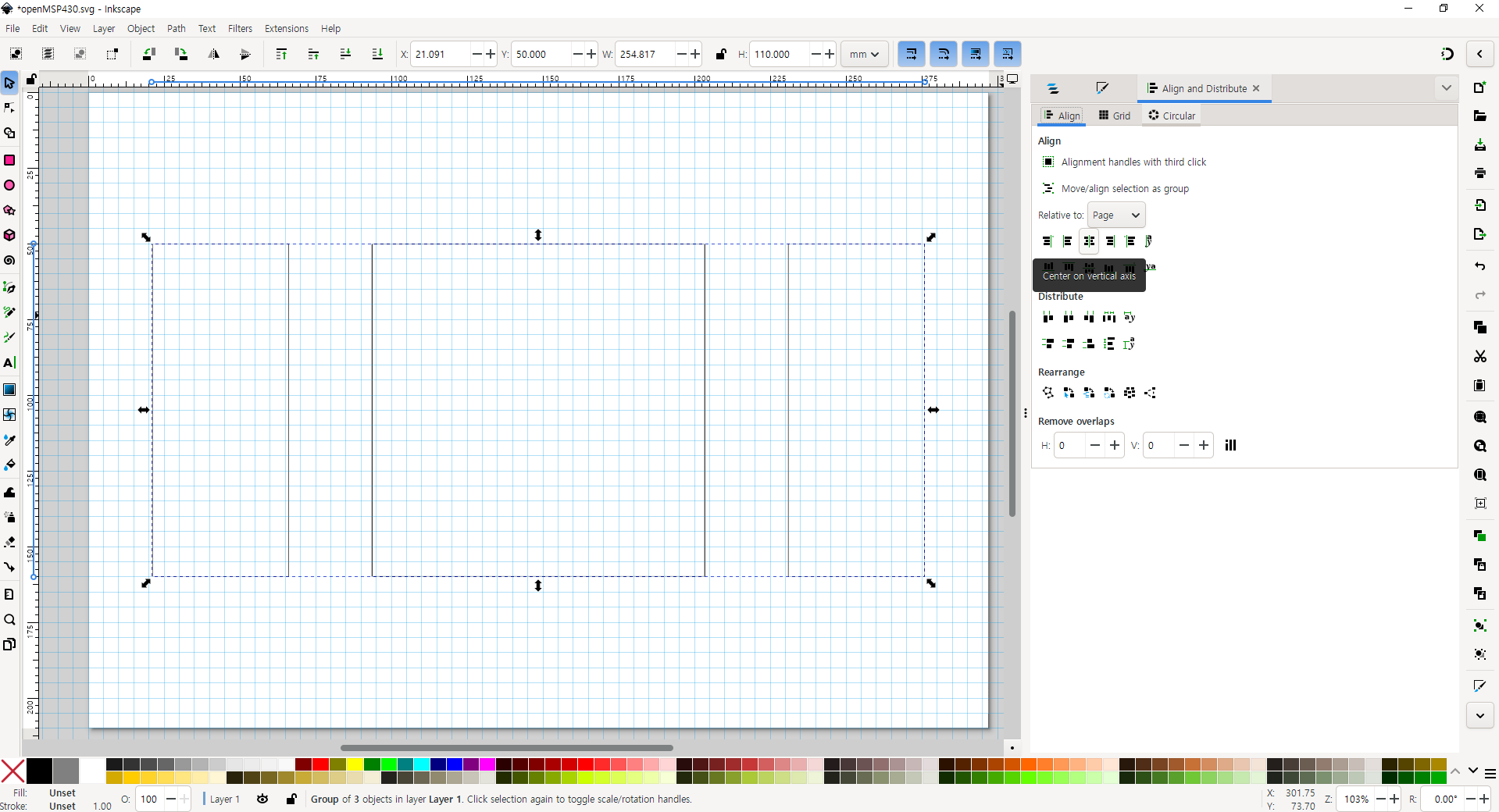
마지막으로 모든 글자와 도형을 드래그한 뒤, 우클릭 - 'Group'을 한 다음, 그룹화된 객체의 디멘션(가로x세로)값을 구한다. 이후 좌측 상단의 'File' - 'Document Properties' 에서 Display 탭의 Width와 Height를 객체의 일의 자리 기준 올림된 디멘션(ex, 256.184x125.960의 경우 260x130)으로 설정한다. 이후 좌측 상단의 'Object' - 'Align and Distribute'에서 'Align' - 'Relative to Page' - 'Center on vertical axis' 및 'Center on horizontal axis'를 클릭한다.

2) 모듈 설계 - HDL
HDL(Hardware Description Language)이란 하드웨어를 기술하기 위한 목적으로 만들어진 프로그래밍 언어이다. HDL을 통해 컴퓨터가 이해할 수 있도록 하드웨어의 기능 및 논리를 코드로 작성할 수 있다. VHDL, Verilog, Chisel, SpinalHDL 등 다양한 언어들이 있지만 이 글에서는 Verilog에 대해 다룰 것이다. 베릴로그 모듈을 작성하기 위해, 우선 Linter 설정 등 베릴로그 코딩 환경을 마련할 필요가 있다. 베릴로그 코딩 환경을 만드는 방법은 아래의 링크를 통해 확인할 수 있다:
(https://zehonyi21.tistory.com/1)
(1)에서 설계한 최종 도면을 HDL로 설계하는 방법은 추후에 시간이 나면 작성하도록 하겠다. 마찬가지로 (3)과 (4)도 여유가 생기면 작성하겠다.
3) 테스트벤치 설계 - 도면
테스트벤치(Testbench)란 테스트를 할 수 있는 벤치, 즉 작업대로 베릴로그에서 테스트벤치는 주어진 모델을 시험해 볼 수 있는 작업공간이라고 할 수 있다.
4) 테스트벤치 설계 - HDL
이제 주어진 테스트벤치를 실제 HDL로 구현하여 실행해볼 시간이다. 일반적인 경우 베릴로그 코딩 환경만 갖추었다면 바로 테스트벤치를 작성할 수 있다. 그러나 이 글에서는 잘 만들어진 테스트벤치 파일과 스크립트를 실행해보기로 한다. 이 과정에서 나는 아래 링크의 도움을 많이 받았다:
(최신버전)(https://github.com/olgirard/openmsp430) 또는
(https://opencores.org/download/openmsp430)
우선 아래 링크의 자료를 다운로드한 다음, core/sim/rtl_sim/bin에 있는 msp430sim을 실행해야 하지만 이 파일은 치명적인 문제가 있다. 아래의 명령어를 입력할 경우 터미널이 종료된다:
source ./msp430sim

원인을 분석하기 위해 파일을 VS Code와 같은 텍스트 에디터로 열어볼 경우 아래와 같은 내용물을 확인할 수 있다:
#!/bin/bash
#------------------------------------------------------------------------------
# Copyright (C) 2001 Authors
#
# This source file may be used and distributed without restriction provided
# that this copyright statement is not removed from the file and that any
# derivative work contains the original copyright notice and the associated
# disclaimer.
#
# This source file is free software; you can redistribute it and/or modify
# it under the terms of the GNU Lesser General Public License as published
# by the Free Software Foundation; either version 2.1 of the License, or
# (at your option) any later version.
#
# This source is distributed in the hope that it will be useful, but WITHOUT
# ANY WARRANTY; without even the implied warranty of MERCHANTABILITY or
# FITNESS FOR A PARTICULAR PURPOSE. See the GNU Lesser General Public
# License for more details.
#
# You should have received a copy of the GNU Lesser General Public License
# along with this source; if not, write to the Free Software Foundation,
# Inc., 51 Franklin Street, Fifth Floor, Boston, MA  02110-1301  USA
#
#------------------------------------------------------------------------------
#
# File Name: msp430sim
#
# Author(s):
#             - Olivier Girard,    olgirard@gmail.com
#
#------------------------------------------------------------------------------
# $Rev$
# $LastChangedBy$
# $LastChangedDate$
#------------------------------------------------------------------------------

###############################################################################
#                            Parse arguments                                  #
###############################################################################
testname=""
seed=""
dma_verif="DMA_VERIF"
while [[ $# > 0 ]]; do
    key="$1"
    shift
    case $key in
	-seed)
	    seed="$1"
	    shift
	    ;;
	-no_dma)
	    dma_verif="NO_DMA_VERIF"
	    ;;
	*)
            testname="$key"
	    ;;
    esac
done

###############################################################################
#                            Parameter Check                                  #
###############################################################################
if [ "$testname" == "" ]; then
  echo "ERROR	 : missing argument"
  echo "USAGE	 : msp430sim <test name> [-seed <seed_nr>] [-no_dma]"
  echo "Example	 : msp430sim c-jump_jge"
  echo ""
  echo "In order to switch the verilog simulator, the OMSP_SIMULATOR environment"
  echo "variable can be set to the following values:"
  echo ""
  echo "		  - iverilog  : Icarus Verilog	(default)"
  echo "		  - cver      : CVer"
  echo "		  - verilog   : Verilog-XL"
  echo "		  - ncverilog : NC-Verilog"
  echo "		  - vcs	      : VCS"
  echo "		  - vsim      : Modelsim"
  echo "		  - isim      : Xilinx simulator"
  echo ""
  exit 1
fi

# Generate random seed if not specified
if [ "$seed" == "" ]; then
    seed=`od -A n -t d -N 4 /dev/urandom`
fi

###############################################################################
#                     Check if the required files exist                       #
###############################################################################
asmfile=../src/$testname.s43;
verfile=../src/$testname.v;
incfile=../../../rtl/verilog/openMSP430_defines.v;
linkfile=../bin/template.x;
headfile=../bin/template_defs.asm;
submitfile=../src/submit.f;
if [ "$OMSP_SIMULATOR" == "isim" ]; then
    submitfile=../src/submit.prj;
fi

if [ ! -e $asmfile ]; then
    echo "Assembler file $asmfile doesn't exist: $asmfile"
    exit 1
fi
if [ ! -e $verfile ]; then
    echo "Verilog stimulus file $verfile doesn't exist: $verfile"
    exit 1
fi
if [ ! -e $submitfile ]; then
    echo "Verilog submit file $submitfile doesn't exist: $submitfile"
    exit 1
fi
if [ ! -e $linkfile ]; then
    echo "Linker definition file template doesn't exist: $linkfile"
    exit 1
fi
if [ ! -e $headfile ]; then
    echo "Assembler definition file template doesn't exist: $headfile"
    exit 1
fi


###############################################################################
#                               Cleanup                                       #
###############################################################################
echo "Cleanup..."
rm -rf *.vcd
rm -rf *.vpd
rm -rf *.trn
rm -rf *.dsn
rm -rf pmem*
rm -rf stimulus.v


###############################################################################
#                              Run simulation                                 #
###############################################################################
echo " ======================================================="
echo "| Start simulation:             $testname"
echo " ======================================================="
echo ""
echo " Seed: $seed"
echo ""

# Create links
if [[ $(uname -s) == CYGWIN* ]];
then
    cp $asmfile pmem.s43
    cp $verfile stimulus.v
else
    ln -s $asmfile pmem.s43
    ln -s $verfile stimulus.v
fi

# Make local copy of the openMSP403 configuration file
# and prepare it for MSPGCC preprocessing
cp  $incfile  ./pmem.h
sed -ie 's/`ifdef/#ifdef/g'         ./pmem.h
sed -ie 's/`else/#else/g'           ./pmem.h
sed -ie 's/`endif/#endif/g'         ./pmem.h
sed -ie 's/`define/#define/g'       ./pmem.h
sed -ie 's/`include/\/\/#include/g' ./pmem.h
sed -ie 's/`//g'                    ./pmem.h
sed -ie "s/'//g"                    ./pmem.h

# Use MSPGCC preprocessor to extract the Program, Data
# and Peripheral memory sizes
if command -v msp430-elf-gcc >/dev/null; then
    msp430-elf-gcc -E -P -x c ../bin/omsp_config.sh > pmem.sh
else
    msp430-gcc     -E -P -x c ../bin/omsp_config.sh > pmem.sh
fi

# Source the extracted configuration file
if [[ $(uname -s) == CYGWIN* ]];
then
dos2unix pmem.sh
fi
source   pmem.sh

# Compile assembler code
echo "Compile, link & generate IHEX file (Program Memory: $pmemsize B, Data Memory: $dmemsize B, Peripheral Space: $persize B)..."
../bin/asm2ihex.sh  pmem pmem.s43 $linkfile $headfile $pmemsize $dmemsize $persize

# Generate Program memory file
echo "Convert IHEX file to Verilog MEMH format..."
../bin/ihex2mem.tcl -ihex pmem.ihex -out pmem.mem -mem_size $pmemsize

# Start verilog simulation
echo "Start Verilog simulation..."
../bin/rtlsim.sh    stimulus.v pmem.mem $submitfile $seed $dma_verif
스크립트를 보면 알 수 있듯이 오류가 생길 때마다 'exit 1'을 입력하기 때문에 터미널이 종료된다.(누군가는 여기서 이 스크립트의 상위 스크립트가 존재할 것이라는 사실을 유추해낼 수 있다.) 따라서 exit 명령어를 주석 처리를 하여 종료 현상을 막을 수 있다:
#!/bin/bash
#------------------------------------------------------------------------------
# Copyright (C) 2001 Authors
#
# This source file may be used and distributed without restriction provided
# that this copyright statement is not removed from the file and that any
# derivative work contains the original copyright notice and the associated
# disclaimer.
#
# This source file is free software; you can redistribute it and/or modify
# it under the terms of the GNU Lesser General Public License as published
# by the Free Software Foundation; either version 2.1 of the License, or
# (at your option) any later version.
#
# This source is distributed in the hope that it will be useful, but WITHOUT
# ANY WARRANTY; without even the implied warranty of MERCHANTABILITY or
# FITNESS FOR A PARTICULAR PURPOSE. See the GNU Lesser General Public
# License for more details.
#
# You should have received a copy of the GNU Lesser General Public License
# along with this source; if not, write to the Free Software Foundation,
# Inc., 51 Franklin Street, Fifth Floor, Boston, MA  02110-1301  USA
#
#------------------------------------------------------------------------------
#
# File Name: msp430sim
#
# Author(s):
#             - Olivier Girard,    olgirard@gmail.com
#
#------------------------------------------------------------------------------
# $Rev$
# $LastChangedBy$
# $LastChangedDate$
#------------------------------------------------------------------------------

###############################################################################
#                            Parse arguments                                  #
###############################################################################
testname=""
seed=""
dma_verif="DMA_VERIF"
while [[ $# > 0 ]]; do
    key="$1"
    shift
    case $key in
	-seed)
	    seed="$1"
	    shift
	    ;;
	-no_dma)
	    dma_verif="NO_DMA_VERIF"
	    ;;
	*)
            testname="$key"
	    ;;
    esac
done

###############################################################################
#                            Parameter Check                                  #
###############################################################################
if [ "$testname" == "" ]; then
  echo "ERROR	 : missing argument"
  echo "USAGE	 : msp430sim <test name> [-seed <seed_nr>] [-no_dma]"
  echo "Example	 : msp430sim c-jump_jge"
  echo ""
  echo "In order to switch the verilog simulator, the OMSP_SIMULATOR environment"
  echo "variable can be set to the following values:"
  echo ""
  echo "		  - iverilog  : Icarus Verilog	(default)"
  echo "		  - cver      : CVer"
  echo "		  - verilog   : Verilog-XL"
  echo "		  - ncverilog : NC-Verilog"
  echo "		  - vcs	      : VCS"
  echo "		  - vsim      : Modelsim"
  echo "		  - isim      : Xilinx simulator"
  echo ""
  # exit 1
fi

# Generate random seed if not specified
if [ "$seed" == "" ]; then
    seed=`od -A n -t d -N 4 /dev/urandom`
fi

###############################################################################
#                     Check if the required files exist                       #
###############################################################################
asmfile=../src/$testname.s43;
verfile=../src/$testname.v;
incfile=../../../rtl/verilog/openMSP430_defines.v;
linkfile=../bin/template.x;
headfile=../bin/template_defs.asm;
submitfile=../src/submit.f;
if [ "$OMSP_SIMULATOR" == "isim" ]; then
    submitfile=../src/submit.prj;
fi

if [ ! -e $asmfile ]; then
    echo "Assembler file $asmfile doesn't exist: $asmfile"
    # exit 1
fi
if [ ! -e $verfile ]; then
    echo "Verilog stimulus file $verfile doesn't exist: $verfile"
    # exit 1
fi
if [ ! -e $submitfile ]; then
    echo "Verilog submit file $submitfile doesn't exist: $submitfile"
    # exit 1
fi
if [ ! -e $linkfile ]; then
    echo "Linker definition file template doesn't exist: $linkfile"
    # exit 1
fi
if [ ! -e $headfile ]; then
    echo "Assembler definition file template doesn't exist: $headfile"
    # exit 1
fi


###############################################################################
#                               Cleanup                                       #
###############################################################################
echo "Cleanup..."
rm -rf *.vcd
rm -rf *.vpd
rm -rf *.trn
rm -rf *.dsn
rm -rf pmem*
rm -rf stimulus.v


###############################################################################
#                              Run simulation                                 #
###############################################################################
echo " ======================================================="
echo "| Start simulation:             $testname"
echo " ======================================================="
echo ""
echo " Seed: $seed"
echo ""

# Create links
if [[ $(uname -s) == CYGWIN* ]];
then
    cp $asmfile pmem.s43
    cp $verfile stimulus.v
else
    ln -s $asmfile pmem.s43
    ln -s $verfile stimulus.v
fi

# Make local copy of the openMSP403 configuration file
# and prepare it for MSPGCC preprocessing
cp  $incfile  ./pmem.h
sed -ie 's/`ifdef/#ifdef/g'         ./pmem.h
sed -ie 's/`else/#else/g'           ./pmem.h
sed -ie 's/`endif/#endif/g'         ./pmem.h
sed -ie 's/`define/#define/g'       ./pmem.h
sed -ie 's/`include/\/\/#include/g' ./pmem.h
sed -ie 's/`//g'                    ./pmem.h
sed -ie "s/'//g"                    ./pmem.h

# Use MSPGCC preprocessor to extract the Program, Data
# and Peripheral memory sizes
if command -v msp430-elf-gcc >/dev/null; then
    msp430-elf-gcc -E -P -x c ../bin/omsp_config.sh > pmem.sh
else
    msp430-gcc     -E -P -x c ../bin/omsp_config.sh > pmem.sh
fi

# Source the extracted configuration file
if [[ $(uname -s) == CYGWIN* ]];
then
dos2unix pmem.sh
fi
source   pmem.sh

# Compile assembler code
echo "Compile, link & generate IHEX file (Program Memory: $pmemsize B, Data Memory: $dmemsize B, Peripheral Space: $persize B)..."
../bin/asm2ihex.sh  pmem pmem.s43 $linkfile $headfile $pmemsize $dmemsize $persize

# Generate Program memory file
echo "Convert IHEX file to Verilog MEMH format..."
../bin/ihex2mem.tcl -ihex pmem.ihex -out pmem.mem -mem_size $pmemsize

# Start verilog simulation
echo "Start Verilog simulation..."
../bin/rtlsim.sh    stimulus.v pmem.mem $submitfile $seed $dma_verif
위 코드가 담긴 파일을 실행하면 오류가 발생해도 터미널이 종료되지 않고 그대로 남아있다.

오류를 자세히 들여다보면 프로그램에 아규먼트로 테스트벤치파일 이름을 입력하지 않아서 오류가 발생하였다. 오류에 적힌 예시를 참조하여 아래와 같은 명령어를 입력할 수 있다:
source ./msp430sim c-jump_jge

오류를 자세히 들여다보면 msp430-gcc가 설치되지 않아 프로그램을 진행할 수 없다는 내용을 확인할 수 있다. 따라서 아래의 명령어를 입력하여 msp430-gcc를 설치할 수 있다:
sudo apt-get install gcc-msp430
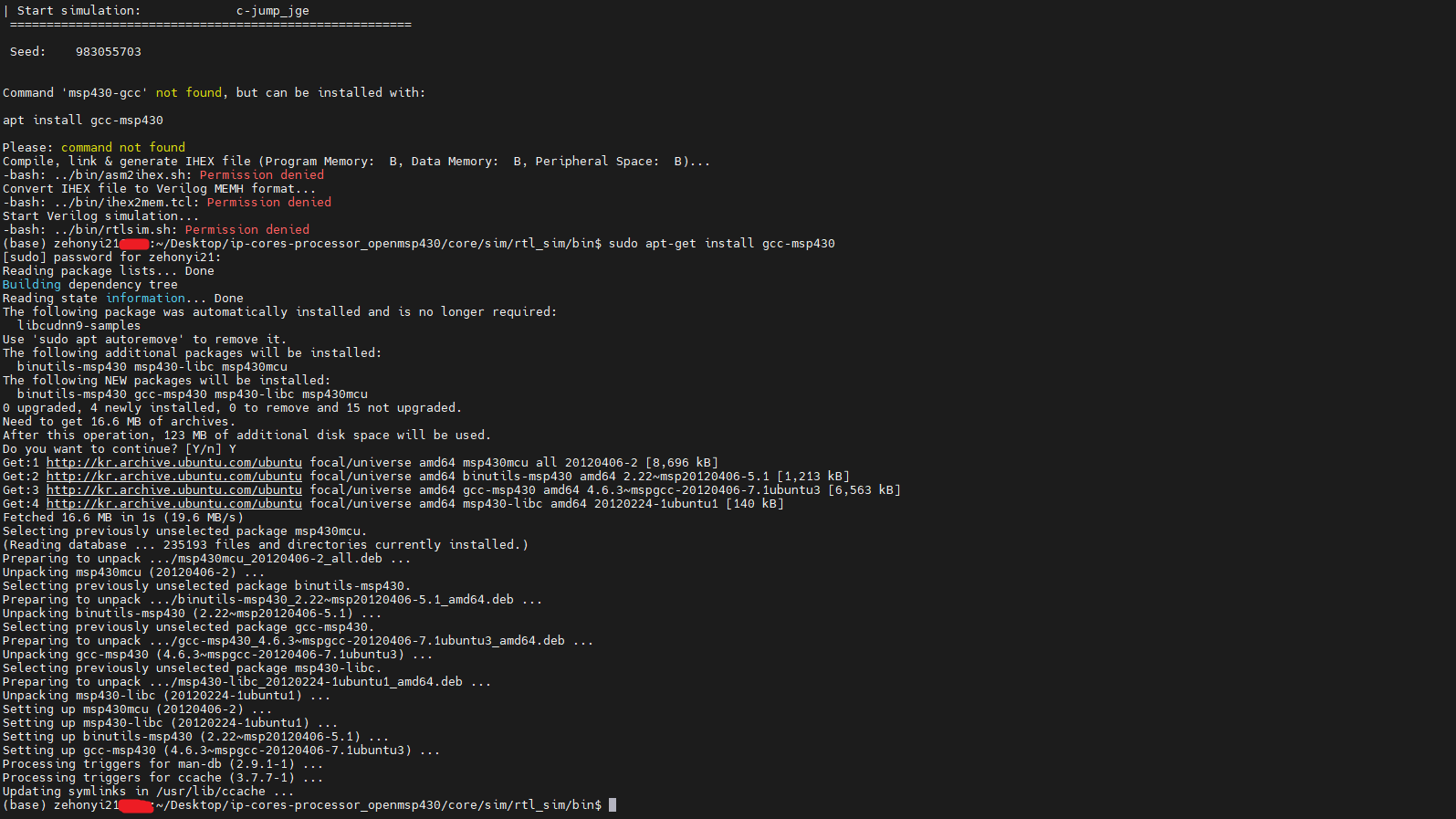
이후 다시 명령어를 실행하면 아래와 같은 결과를 얻을 수 있다:

오류를 자세히 들여다보면 '../run/pmem.h'파일을 찾을 수 없다는 문제를 확인할 수 있다. 위에 명시된 msp430sim 파일의 스크립트를 확인해보면 알 수 있듯이 pmem.h파일은 ../run 폴더가 아니라 현재 경로, 즉 ./에 있다. 따라서 omsp_config.sh 파일을 아래와 같이 수정한다:
#include "./pmem.h"

pmemsize=PMEM_SIZE
dmemsize=DMEM_SIZE
persize=PER_SIZE
누군가는 쉘 스크립트 명령어에 #이 있는데 왜 주석이 아니라 명령어로 인식하는지 궁금해할 수 있다. msp430sim의 스크립트를 보면 msp430-gcc관련 명령어가 나오는데 이 명령어에 한해 c언어로 파일을 수행하도록 옵션을 설정했기 때문이다. 다시 msp430sim을 실행시키면 아래와 같은 결과를 얻을 수 있다:
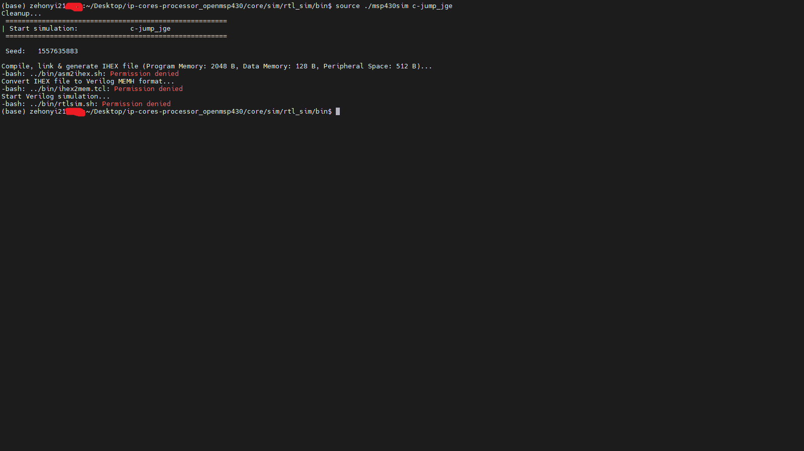
오류를 자세히 들여다보면 권한이 없어서 주어진 쉘 스크립트 또는 tcl 파일을 실행할 수 없다는 사실을 확인할 수 있다. 따라서 아래의 명령어를 입력하여 파일들의 권한을 상승시킬 수 있다:
chmod 777 ../bin/asm2ihex.sh
chmod 777 ../bin/ihex2mem.tcl
chmod 777 ../bin/rtlsim.sh
다시 msp430sim을 실행시키면 아래와 같은 결과를 얻을 수 있다:

오류를 자세히 들여다보면 tclsh을 설치하지 않았다는 사실을 확인할 수 있다. tclsh은 tcl 설치 시 자동으로 설치된다. 따라서 아래 명령어를 입력하여 tcl을 설치한다. 이 과정에서 나는 아래 링크의 도움을 많이 받았다:
sudo apt-get install tcl
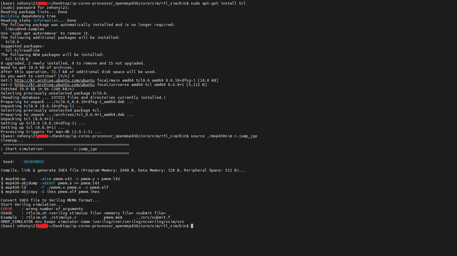
오류를 자세히 들여다보면 명령어에 필요한 아규먼트 수가 부족하다는 사실을 확인할 수 있다.
원래라면 이를 분석하기 위해 어떤 아규먼트가 입력되었는지, 그리고 아규먼트의 개수가 몇개인지 터미널에 출력해주는 명령어를 추가해야 하지만 실은 이 오류는 tcl을 설치한 다음 쉘을 재시작하지 않아서 발생한 버그이다. 터미널을 끄고 새로운 터미널을 불러온 다음 msp430sim을 실행시키면 아래와 같은 결과를 얻을 수 있다:

이때 주어진 시뮬레이션의 파형이 담긴 정보인 tb_openMSP430.vcd가 생성된 사실을 확인할 수 있다. 아래의 명령어를 입력하여 파형을 관찰할 수 있다:
gtkwave tb_openMSP430.vcd

이 파형을 통해 알 수 있듯이 r15(core/bench/verilog/registers.v를 통해 알 수 있듯이 dut.execution_unit_0.register_file_0.r15와 연결되어 있다.)의 값에 자극을 줄 때
r4(dut.execution_unit_0.register_file_0.r4),
r5(dut.execution_unit_0.register_file_0.r5),
r6(dut.execution_unit_0.register_file_0.r6)의 값 변화 여부를 관찰할 수 있다. 이때 register_file_0 인스턴스의 클래스(모듈)는 core/rtl/verilog/omsp_register_file.v에서 확인할 수 있다.
위에서 진행한 HDL 테스트벤치는 'Icarus Verilog '라는 HDL 시뮬레이터로 실행하였다. 누군가는 'Synopsys VCS라는 HDL 시뮬레이터로 테스트벤치를 진행할 순 없을까' 하고 생각할 수 있다. 당연히 가능하다.
먼저 아래에 있는 2번의(0), (7), 그리고 (8)을 참조하여 레드햇 리눅스 운영체제에 VCS와 Verdi(선택적)를 설치해야 한다. 그리고 위 과정을 통해 수정된 파일을 가져와야 한다. 이때 레드햇 리눅스의 경우 msp430-gcc대신 msp430-elf-gcc를 설치해야 한다. 설치파일은 아래 링크를 통해 다운로드할 수 있다:
(https://www.ti.com/tool/MSP430-GCC-OPENSOURCE#downloads) 또는
이후 아무 폴더에서 root 계정으로 실행해야 한다. 명령어는 아래와 같다:
su
./msp430-gcc-full-linux-x64-installer-9.3.1.2.run

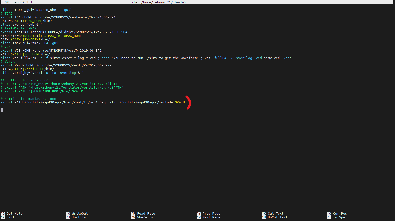
설치가 끝난 뒤, 환경변수(PATH) 설정을 해야 한다. 명령어는 아래와 같다:
nano ~/.bashrc

# Setting for msp430-elf-gcc
export PATH=/root/ti/msp430-gcc/bin:/root/ti/msp430-gcc/lib:/root/ti/msp430-gcc/include:$PATH

source ~/.bashrc
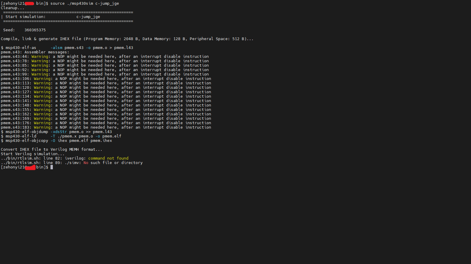
새로운 환경변수를 source한 다음 core/sim/rtl_sim/bin에 있는 msp430sim을 실행해야 한다. 명령어는 아래와 같다:
source ./msp430sim c-jump_jge

오류를 자세히 들여다보면 레드햇 리눅스에 설치한 msp430-elf 명령어가 아닌 msp430 명령어를 사용하고 있는 현상을 확인할 수 있다. 이를 해결하기 위해 asm2ihex.sh를 아래와 같이 수정한다:
#!/bin/bash
#------------------------------------------------------------------------------
# Copyright (C) 2001 Authors
#
# This source file may be used and distributed without restriction provided
# that this copyright statement is not removed from the file and that any
# derivative work contains the original copyright notice and the associated
# disclaimer.
#
# This source file is free software; you can redistribute it and/or modify
# it under the terms of the GNU Lesser General Public License as published
# by the Free Software Foundation; either version 2.1 of the License, or
# (at your option) any later version.1
#
# This source is distributed in the hope that it will be useful, but WITHOUT
# ANY WARRANTY; without even the implied warranty of MERCHANTABILITY or
# FITNESS FOR A PARTICULAR PURPOSE. See the GNU Lesser General Public
# License for more details.
#
# You should have received a copy of the GNU Lesser General Public License
# along with this source; if not, write to the Free Software Foundation,
# Inc., 51 Franklin Street, Fifth Floor, Boston, MA  02110-1301  USA
#
#------------------------------------------------------------------------------
#
# File Name: asm2ihex.sh
#
# Author(s):
#             - Olivier Girard,    olgirard@gmail.com
#
#------------------------------------------------------------------------------
# $Rev$
# $LastChangedBy$
# $LastChangedDate$
#------------------------------------------------------------------------------

###############################################################################
#                            Parameter Check                                  #
###############################################################################
EXPECTED_ARGS=7
if [ $# -ne $EXPECTED_ARGS ]; then
  echo "ERROR    : wrong number of arguments"
  echo "USAGE    : asm2ihex.sh <test name> <test assembler file> <linker script> <assembler define>  <prog mem size> <data mem size> <peripheral addr space size>"
  echo "Example  : asm2ihex.sh c-jump_jge  ../src/c-jump_jge.s43 ../bin/template.x ../bin/pmem.h 2048            128             512"
  exit 1
fi

# MSPGCC version prefix
if [ -z "$MSPGCC_PFX" ]; then
    if command -v msp430-elf-gcc >/dev/null; then
	MSPGCC_PFX=msp430-elf
    else
	MSPGCC_PFX=msp430
    fi
fi

###############################################################################
#               Check if definition & assembler files exist                   #
###############################################################################

if [ ! -e $2 ]; then
    echo "Assembler file doesn't exist: $2"
    exit 1
fi
if [ ! -e $3 ]; then
    echo "Linker definition file template doesn't exist: $3"
    exit 1
fi
if [ ! -e $4 ]; then
    echo "Assembler definition file template doesn't exist: $4"
    exit 1
fi


###############################################################################
#               Generate the linker definition file                           #
###############################################################################

PER_SIZE=$7
DMEM_SIZE=$6
PMEM_SIZE=$5
PMEM_BASE=$((0x10000-$PMEM_SIZE))
STACK_INIT=$((PER_SIZE+0x0080))

cp  $3  ./pmem.x
cp  $4  ./pmem_defs.asm
sed -ie "s/PMEM_BASE/$PMEM_BASE/g"         pmem.x
sed -ie "s/PMEM_SIZE/$PMEM_SIZE/g"         pmem.x
sed -ie "s/DMEM_SIZE/$DMEM_SIZE/g"         pmem.x
sed -ie "s/PER_SIZE/$PER_SIZE/g"           pmem.x
sed -ie "s/STACK_INIT/$STACK_INIT/g"       pmem.x

sed -ie "s/PMEM_SIZE/$PMEM_SIZE/g"         pmem_defs.asm
sed -ie "s/PER_SIZE_HEX/$PER_SIZE/g"       pmem_defs.asm
if [ $MSPGCC_PFX == "msp430-elf" ]; then
    sed -ie "s/PER_SIZE/.data/g"           pmem_defs.asm
    sed -ie "s/PMEM_BASE_VAL/.text/g"      pmem_defs.asm
    sed -ie "s/PMEM_EDE_SIZE/0/g"          pmem_defs.asm
else
    sed -ie "s/PER_SIZE/$PER_SIZE/g"       pmem_defs.asm
    sed -ie "s/PMEM_BASE_VAL/$PMEM_BASE/g" pmem_defs.asm
    sed -ie "s/PMEM_EDE_SIZE/$PMEM_SIZE/g" pmem_defs.asm
fi


###############################################################################
#                  Compile, link & generate IHEX file                         #
###############################################################################
echo ""
echo "\$ $MSPGCC_PFX-as      -alsm $2 -o $1.o > $1.l43"
$MSPGCC_PFX-as      -alsm         $2     -o $1.o     > $1.l43
echo "\$ $MSPGCC_PFX-objdump -xdsStr $1.o >> $1.l43"
$MSPGCC_PFX-objdump -xdsStr       $1.o              >> $1.l43
echo "\$ $MSPGCC_PFX-ld      -T ./pmem.x $1.o -o $1.elf"
$MSPGCC_PFX-ld      -T ./pmem.x   $1.o   -o $1.elf
echo "\$ $MSPGCC_PFX-objcopy -O ihex $1.elf $1.ihex"
$MSPGCC_PFX-objcopy -O ihex       $1.elf    $1.ihex
echo ""
다시 msp430sim을 실행시키면 아래와 같은 결과를 얻을 수 있다:
오류를 자세히 들여다보면 시뮬레이터로 iverilog, 즉 Icarus Verilog가 설정된 모습을 확인할 수 있다. 이를 변경하려면 OMSP_SIMULATOR 변수를 iverilog에서 vcs로 변경해야 한다. OMSP_SIMULATOR 변수는 msp430sim보다 상위 스크립트인 core/sim/rtl_sim/run/run 파일에 있다. 이 파일 또한 msp430-elf 관련 명령어 변경이 필요하다. 두 사항을 반영한 스크립트는 아래와 같다:
#!/bin/bash

# Enable/Disable waveform dumping
OMSP_NODUMP=0
export OMSP_NODUMP

# Choose GCC toolchain prefix ('msp430' for MSPGCC / 'msp430-elf' for GCC RedHat/TI)
# Note: default to MSPGCC until GCC RedHat/TI is mature enough
if command -v msp430-elf-gcc >/dev/null; then
    MSPGCC_PFX=msp430-elf
else
    MSPGCC_PFX=msp430
fi
#MSPGCC_PFX=msp430-elf
export MSPGCC_PFX

# Choose simulator:
#                   - iverilog  : Icarus Verilog  (default)
#                   - cver      : CVer
#                   - verilog   : Verilog-XL
#                   - ncverilog : NC-Verilog
#                   - vcs       : VCS
#                   - vsim      : Modelsim
#                   - isim      : Xilinx simulator
OMSP_SIMULATOR=vcs
export OMSP_SIMULATOR

rm -rf cov_work

../bin/msp430sim two-op_mov
이제 run 파일이 msp430sim을 읽거나 쓸 수 있도록 권한을 상승시켜준 뒤, run 파일을 직접 실행해야 한다. core/sim/rtl_sim/run 폴더 기준 아래 명령어를 통해 권한 상승 및 실행을 진행할 수 있다:
chmod 777 ../bin/msp430sim
source run

이때 주어진 시뮬레이션의 파형이 담긴 정보인 tb_openMSP430.vpd가 생성된 사실을 확인할 수 있다. vpd파일의 경우 VDE(Discovery Visualization Environment)라는 RTL 파형 시뮬레이션 프로그램을 통해 파형을 관찰할 수 있지만 현재는 주로 vcd파일이나 fsdb파일을 자주 사용하기 때문에 거의 사용되지 않고 있다. 따라서 이 글에서는 Synopsys VCS를 사용하여 vpd파일을 vcd파일로 변환한 다음 GTKWave를 사용하여 파형을 관찰할 것이다. 변환 명령어는 아래와 같다:
vcs -vpd2vcd tb_openMSP430.vpd tb_openMSP430.vcd

아래의 명령어를 입력하여 파형을 관찰할 수 있다:
gtkwave tb_openMSP430.vcd

이 파형을 통해 알 수 있듯이 r15(core/bench/verilog/registers.v를 통해 알 수 있듯이 dut.execution_unit_0.register_file_0.r15와 연결되어 있다.)의 값에 자극을 줄 때
mem200 - mem27E(core/bench/verilog/registers.v를 통해 알 수 있듯이
dmem_0.mem[0] - dmem_0.mem[63]와 연결되어 있다.)의 값 변화 여부를 관찰할 수 있다. 이때 dmem_0 인스턴스의 클래스(모듈)은 core/bench/verilog/ram.v에서 확인할 수 있다.
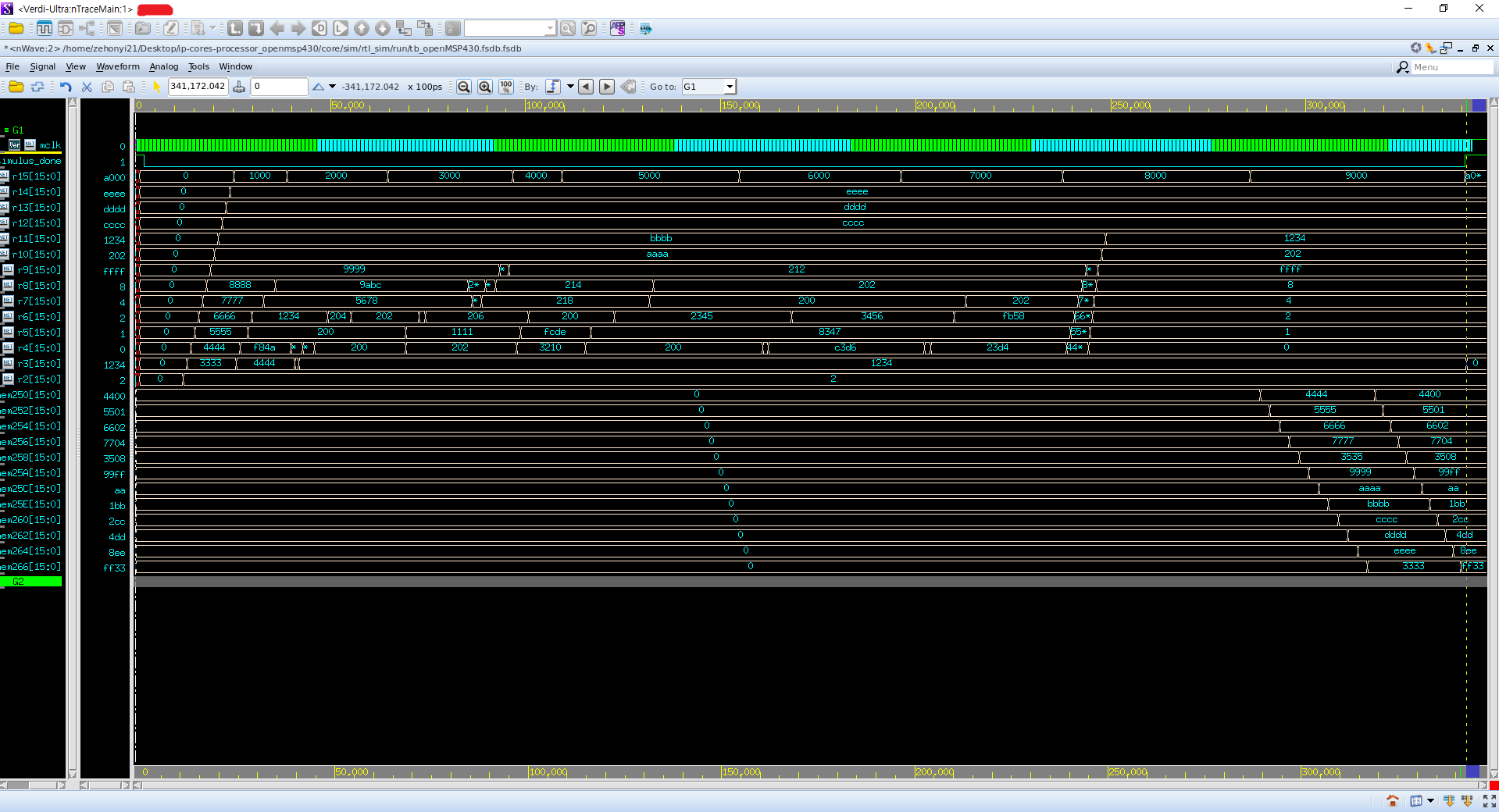
누군가는 'fsdb파일로 파형을 관찰할 순 없을까' 하고 생각할 수 있다. 당연히 가능하다. core/bench/verilog/tb_openMSP430.v의 'Generate Waveform'와 core/sim/rtl_sim/bin/rtlsim.sh의 'Start verilog simulation'만 다음과 같이 수정해주면 된다:
//
// Generate Waveform
//----------------------------------------
initial
  begin
   `ifdef NODUMP
   `else
     `ifdef FSDB_FILE
        $dumpfile("tb_openMSP430.fsdb");
        $dumpvars(0, tb_openMSP430);
      `else
        `ifdef VPD_FILE
          $vcdplusfile("tb_openMSP430.vpd");
          $vcdpluson();
        `else
          `ifdef TRN_FILE
            $recordfile ("tb_openMSP430.trn");
            $recordvars;
          `else
            $dumpfile("tb_openMSP430.vcd");
            $dumpvars(0, tb_openMSP430);
          `endif
        `endif
      `endif
   `endif
  end
###############################################################################
#                         Start verilog simulation                            #
###############################################################################

if [ "${OMSP_SIMULATOR:-iverilog}" = iverilog ]; then

    rm -rf simv

    NODUMP=${OMSP_NODUMP-0}
    if [ $NODUMP -eq 1 ]
      then
        iverilog -o simv -c $3 -D SEED=$4 -D $5 -D NODUMP
      else
        iverilog -o simv -c $3 -D SEED=$4 -D $5
    fi

    if [[ $(uname -s) == CYGWIN* ]];
    then
     	vvp.exe ./simv
    else
        ./simv
    fi

else

    NODUMP=${OMSP_NODUMP-0}
    if [ $NODUMP -eq 1 ] ; then
       vargs="+define+SEED=$4 +define+$5 +define+NODUMP"
    else
       vargs="+define+SEED=$4 +define+$5"
    fi

   case $OMSP_SIMULATOR in
    cver* )
       vargs="$vargs +define+VXL +define+CVER" ;;
    verilog* )
       vargs="$vargs +define+VXL" ;;
    ncverilog* )
       rm -rf INCA_libs
       #vargs="$vargs +access+r +nclicq +ncinput+../bin/cov_ncverilog.tcl -covdut openMSP430 -covfile ../bin/cov_ncverilog.ccf -coverage all +define+TRN_FILE" ;;
       vargs="$vargs +access+r +svseed=$4 +nclicq +define+TRN_FILE" ;;
    vcs* )
       rm -rf csrc simv*
       vargs="$vargs -R -debug_pp +vcs+lic+wait +v2k +define+FSDB_FILE" ;;
    vsim* )
       # Modelsim
       if [ -d work ]; then  vdel -all; fi
       vlib work
       exec vlog +acc=prn -f $3 $vargs -R -c -do "run -all" ;;
    isim )
       # Xilinx simulator
       rm -rf fuse* isim*
       fuse tb_openMSP430 -prj $3 -o isim.exe -i ../../../bench/verilog/ -i ../../../rtl/verilog/ -i ../../../rtl/verilog/periph/
       echo "run all" > isim.tcl
       ./isim.exe -tclbatch isim.tcl
       exit
   esac

   echo "Running: $OMSP_SIMULATOR -f $3 $vargs"
   exec $OMSP_SIMULATOR -f $3 $vargs
fi

이 fsdb파일을 Verdi를 통해 열어볼 수 있다. 명령어는 아래와 같다:
verdi_bg

이후 Verdi 화면에서 왼쪽 상단의 'File' - 'Open Waveform File'을 누른 다음, 'tb_openMSP430.fsdb'를 선택한다.

이후 왼쪽 아래 'Signal' - 'Get Signals...'를 클릭하여 원하는 신호를 불러온다:

2. 합성
합성은 RTL에 라이브러리 정보를 연결하는 과정이다. 이 과정에서 특정 공정에서 사용되는 게이트들이 RTL에 적용된다. 위에서 말했던 레고 조립 설명서의 비유에서 레고 블럭의 크기와 모델 번호를 하나하나 입력하는 과정이라고 생각할 수 있다. 합성을 진행하기 위해서는 합성 프로그램(이 글에서는 Synopsys의 Design Compiler)과 합성 명령어 꾸러미인 스크립트가 필요하다.
합성 프로그램을 설치하기 위해 우선 VLSI CAD Tool을 설치할 필요가 있다. VLSI CAD Tool은 집적 회로를 설계할 때 필요한 컴퓨터 프로그램이다. 과거에 디지털 회로를 설계할 때는 수기로 회로 도면을 그렸지만 컴퓨터의 발명으로 인해 간단한 명령어만으로도 복잡한 회로를 설계할 수 있게 되었다. Cadence, Synopsys 등 다양한 회사가 VLSI CAD Tool을 제공하고 있다. 이 글에서는 그 회사들 중 하나인 Synopsys의 VLSI CAD Tool을 사용하려 한다. 필요한 프로그램들은 아래와 같다:
-------------------------------------------------------------------------------------------------------
0) 레드햇 리눅스 운영체제
1) Design_Compiler(합성 및 DFT 삽입 프로그램)
2) Formality(기능성 검증 프로그램)
3) ICC2(레이아웃 프로그램)
4) PrimeTime(Static Timing Analysis 프로그램)
5) StarRC(기생 RC 추출 프로그램)
6) TestMAX_TetraMAX(Automatic Test Pattern Generation 프로그램)
7) VCS(RTL CLI 시뮬레이션 프로그램)
8) Verdi(RTL 파형 시뮬레이션 프로그램)
-------------------------------------------------------------------------------------------------------
이 프로그램들을 설치하는 방법은 아래의 링크에 잘 설명되어있다:
(https://zehonyi21.tistory.com/2)
위 글은 좋은 정보를 담고 있지만 운영체제가 상대적으로 구식이다. 즉 날짜가 너무 오래되어 새로운 운영체제를 바탕으로 위에 명시된 프로그램들을 설치할 때 유용한 글이 아니다. 따라서 우리는 상대적으로 최신 방식을 사용하여 위 프로그램들을 설치하려 한다.
0) 레드햇 리눅스 운영체제
리눅스를 처음 설치하는 사람들은 대부분 Ubuntu를 설치해 본 적이 있을 것이다. 그러나 Synopsys의 프로그램들은 Ubuntu 운영체제(데비안 기반)에서 돌아가지 않는다. 따라서 우리는 페도라 기반의 레드햇 리눅스 운영체제들 중 하나를 설치할 것이다. 레드햇 리눅스 운영체제들 중 유명한 것들을 나열하자면 RHEL(Red Hat Enterprise Linux), (구)CentOS, Rocky Linux, Oracle Linux, AlmaLinux 등이 있다. 이중에서 RHEL과 Oracle Linux는 기업에서 많이 사용하기에 개인용으로 사용하려면 Rocky Linux나 AlmaLinux가 무난하다. 두 OS 모두 경쟁력이 있지만 이 글에서는 WSL에서 설치하기 쉬운 AlmaLinux 위주로 설명할 것이며 설치를 마친 이후에는 (구)CentOS 환경을 사용하겠다.(라이선스 포트 문제가 발생했다.)
우선 AlmaLinux를 설치해야 한다. 데스크탑에 직접 설치해도 좋고 WSL을 통해 윈도우에 설치해도 좋다. 설치 결과 아래와 같은 화면을 얻을 수 있다:

이후 Synopsys VLSI CAD Tool을 설치하기 위해 필요한 기초적인 프로그램 및 라이브러리들을 다운받아야 한다. 아래의 명령어를 입력하여 설치할 수 있다. 이때 'Error: Unable to find a match:'가 나올 수 있다. 가볍게 무시해도 좋다.
sudo dnf install yum
sudo yum -y install ftp libXt* libXt*.i686 libXext* libXext*.i686 libXScrnSaver libXScrnSaver.i686 ncurses* ncurses*.i686 sblim* ksh* libgl* libgl*.i686 mesa-* mesa-*.i686 libXp libXp.i686 libXrender libXrender.i686 glibc* glibc*.i686 fftw libreadline* libreadline*.i686 openmotif* openmotif*.i686 compat-readline* compat-readline*.i686 xorg*font* xterm redhat-lsb redhat-lsb.i686
sudo yum -y install libX* lsb motif libnsl pulseaudio*
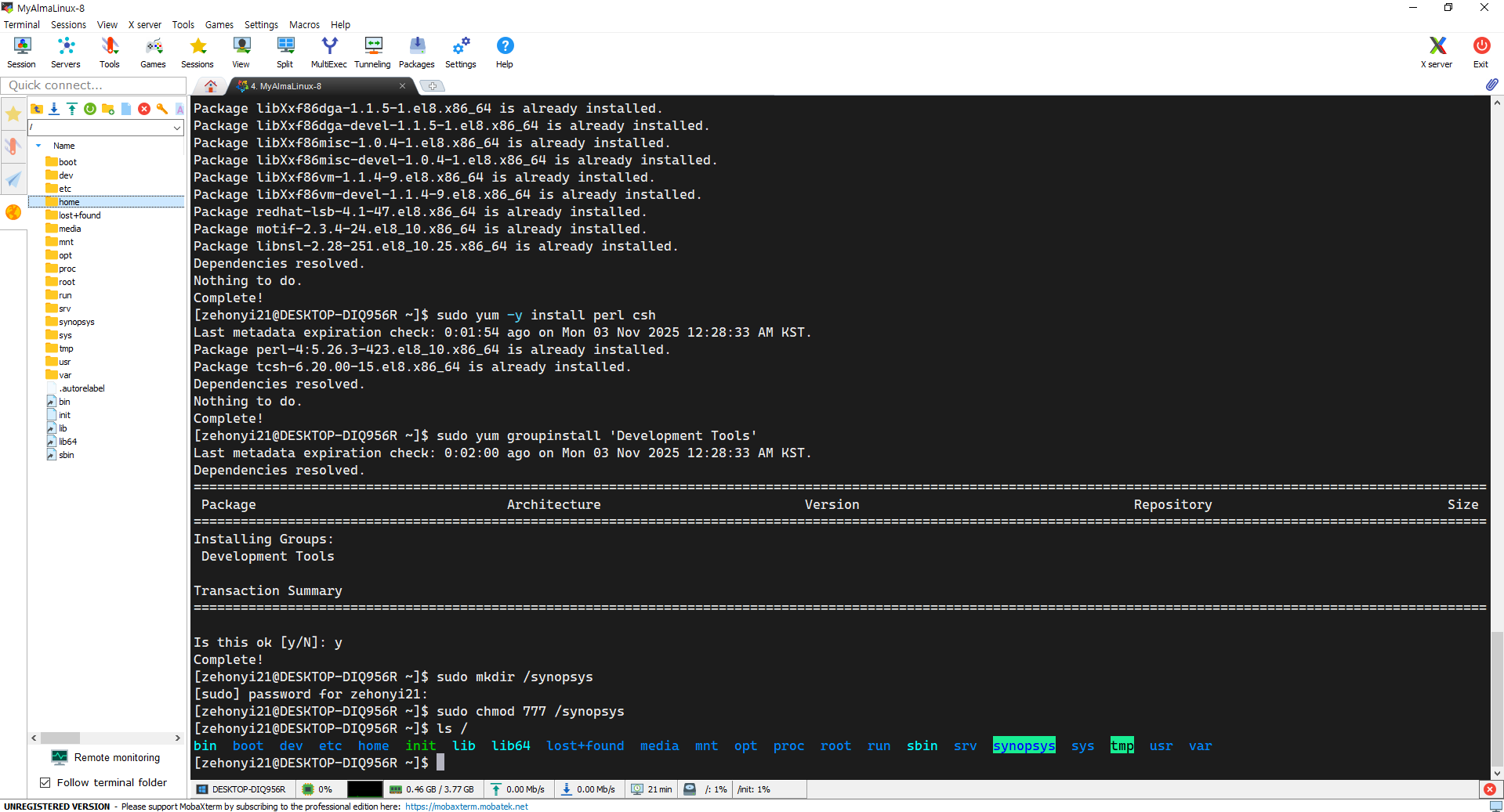
sudo yum -y install perl csh
sudo yum groupinstall 'Development Tools'

1) Design_Compiler(스키메틱 디자인 및 베리피케이션 프로그램)
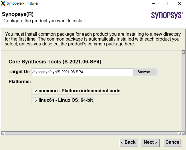
Design_Compiler는 대표적인 스키메틱 디자인 및 베리피케이션 프로그램으로, 베릴로그 파일 내부의 High-Level 논리 명령어들을 전부 Low-Level 게이트로 바꾸는 기능을 포함하여 게이트에 공정 정보를 삽입하거나 주어진 주파수 내에서 딜레이 오류 없이 회로가 작동할 수 있는지 분석해 주는 베리피케이션 기능도 담당하는 다재다능한 프로그램이다. 이 프로그램을 설치하기 위해 Synopsys로부터 압축 파일인 SPF 파일(*.spf)을 다운받은 뒤, 전용 설치 프로그램을 실행시켜야 한다. 우선 Design_Compiler가 설치될 경로를 결정해야 한다. 설치하고 싶은 경로(ex, /(루트 경로))에 'synopsys' 폴더를 생성한 뒤, 다른 사용자들이 쉽게 읽고 쓸 수 있도록 권한을 설정해줘야 한다. 명령어는 아래와 같다:
sudo mkdir /synopsys
sudo chmod 777 /synopsys
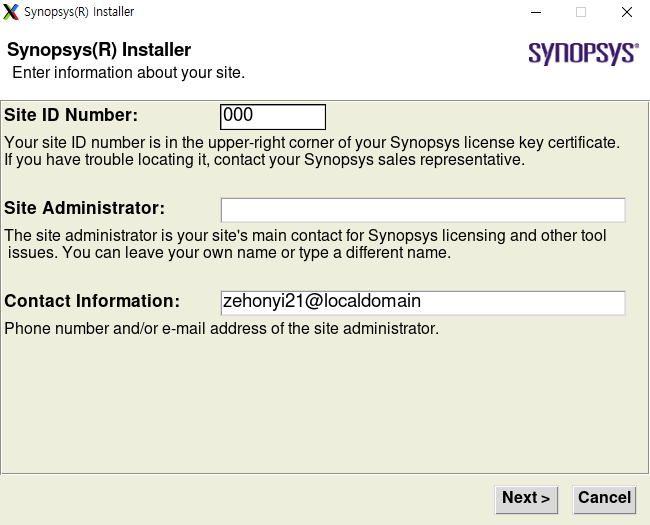
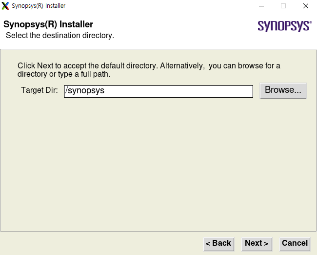
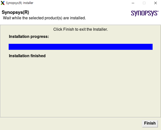
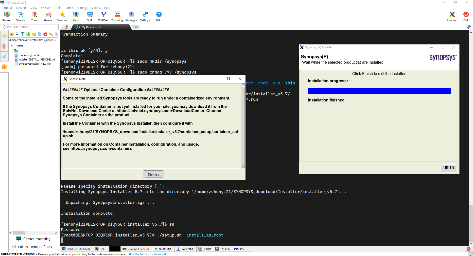
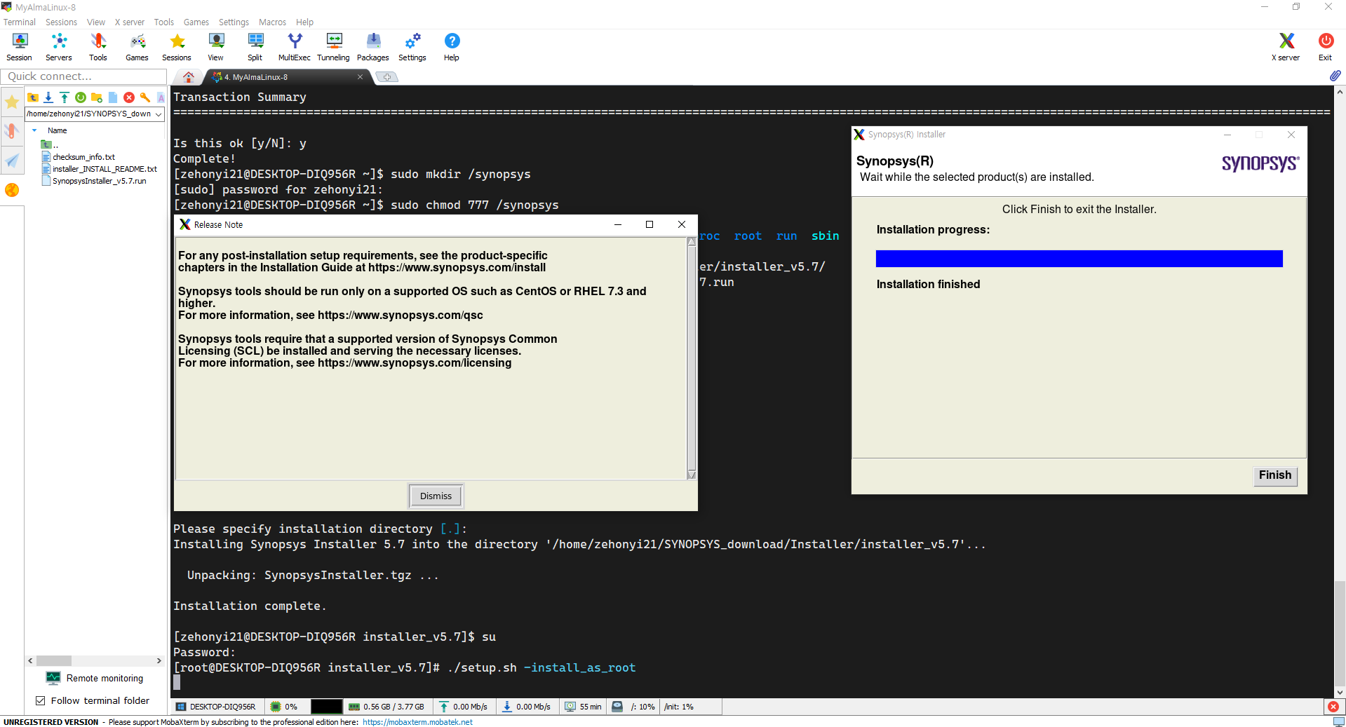
이후 설치 프로그램을 실행시켜야 한다. 아래와 비슷한 명령어를 적용할 수 있다:
chmod 777 SynopsysInstaller_v5.7.run
./SynopsysInstaller_v5.7.run
(enter)
su
(enter password)
./setup.sh -install_as_root


이후 환경변수를 설정하여 어느 경로에서라도 Design_Compiler를 실행시킬 수 있다. 명령어는 아래와 같다:
nano ~/.bashrc

# License
export SNPSLMD_LICENSE_FILE=27020@111.111.111.111
# Design_Compiler
export Design_Compiler_HOME=/synopsys/syn/S-2021.06-SP4
PATH=$PATH:$Design_Compiler_HOME/bin/
alias dc_gui='dc_shell -64bit -gui'
# Formality
export Formality_HOME=/synopsys/fm/S-2021.06
SYNOPSYS=$SYNOPSYS:$Formality_HOME
PATH=$PATH:$Formality_HOME/bin/
alias fm_gui='fm_shell -gui'
# Hspice
export Hspice_HOME=/synopsys/hspice/S-2021.09
PATH=$PATH:$Hspice_HOME/hspice/bin
alias hspice_help='hspice -h'
# ICC
export ICC_HOME=/synopsys/icc/S-2021.06
PATH=$PATH:$ICC_HOME/bin/
alias icc_gui='icc_shell -64bit -gui'
# ICC2
export ICC2_HOME=/synopsys/icc2/S-2021.06
PATH=$PATH:$ICC2_HOME/bin/
alias icc2_gui='icc2_shell -64bit -gui'
# Library_Compiler
export SYNOPSYS_LC_ROOT=/d_drive/SYNOPSYS/lc/S-2021.06
PATH=$PATH:$SYNOPSYS_LC_ROOT/bin/
alias lc_gui='lc_shell -64bit -gui'
# Milkyway
export Milkyway_HOME=/synopsys/mw/N-2017.09
PATH=$PATH:$Milkyway_HOME/bin/linux64/
alias Milkyway_gui='Milkyway -tcl'
# PrimeTime
export PrimeTime_HOME=/synopsys/prime/S-2021.06
PATH=$PATH:$PrimeTime_HOME/bin/
alias pt_gui='pt_shell -gui'
# StarRC
export StarRC_HOME=/synopsys/starrc/S-2021.06
PATH=$PATH:$StarRC_HOME/bin/
alias starrc_gui='starrc_shell -gui'
# TCAD
export TCAD_HOME=/synopsys/sentaurus/S-2021.06-SP1
PATH=$PATH:$TCAD_HOME/bin/
alias swb_bg='swb & '
# TestMAX_TetraMAX
export TestMAX_TetraMAX_HOME=/synopsys/txs/S-2021.06-SP4
SYNOPSYS=$SYNOPSYS:$TestMAX_TetraMAX_HOME
PATH=$PATH:$SYNOPSYS/bin/
alias tmax_gui='tmax -64 -gui'
# VCS
export VCS_HOME=/synopsys/vcs/P-2019.06-SP1
PATH=$PATH:$VCS_HOME/bin/
alias vcs_full='rm -r -f simv* csrc* *.log *.vcd ; echo "You need to run ./simv to get the waveform" ; vcs -full64 -V -sverilog -vcd simv.vcd'
# Verdi
export Verdi_HOME=/synopsys/verdi/P-2019.06-SP2-5
PATH=$PATH:$Verdi_HOME/bin/
alias verdi_bg='verdi -ultra -sverilog & '
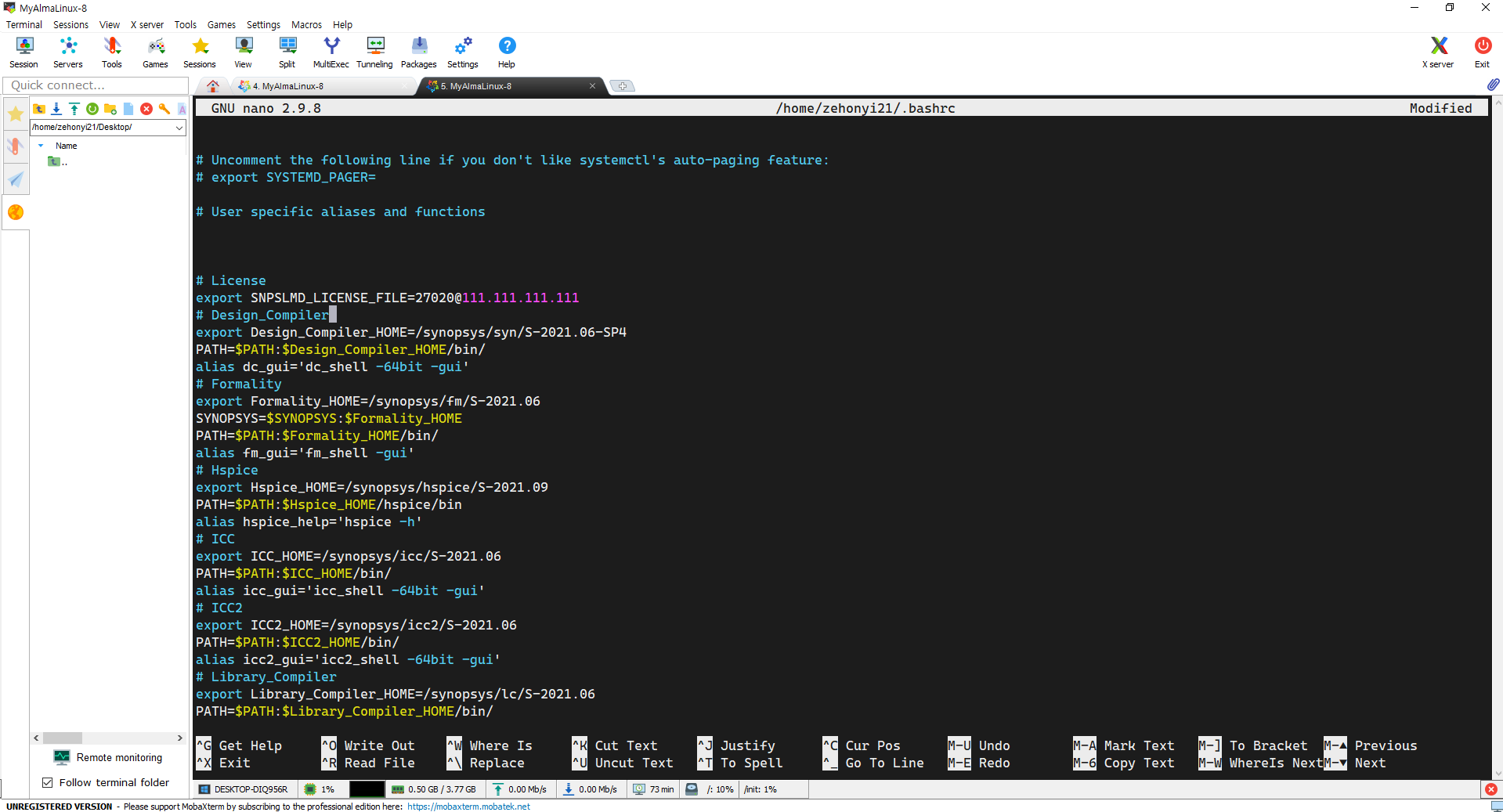
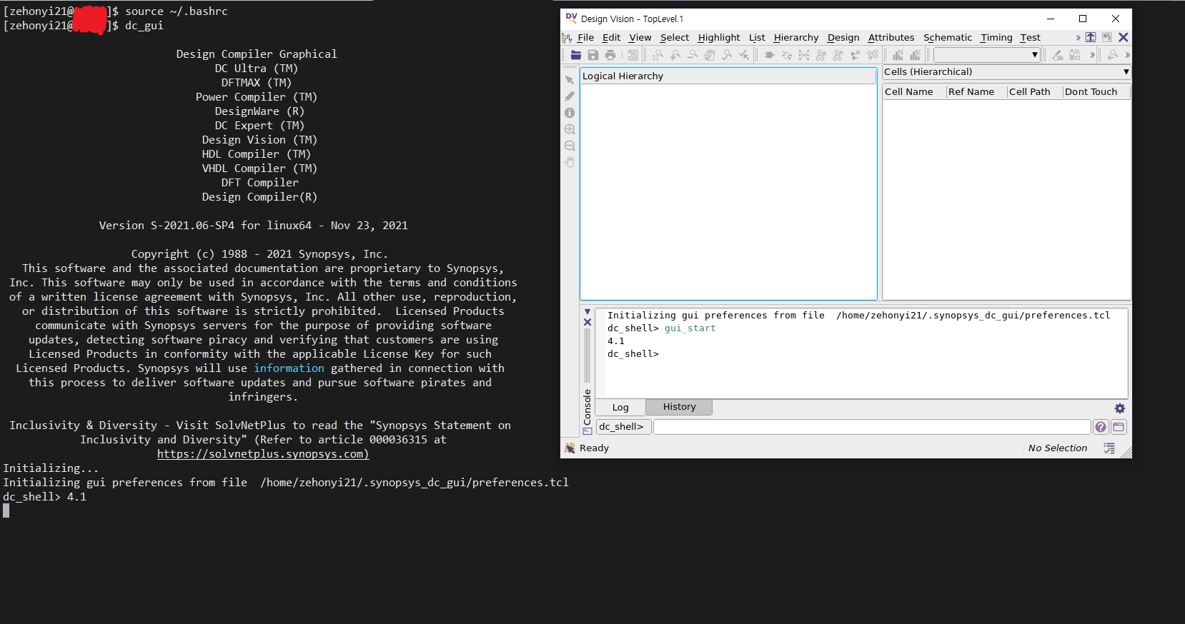
아래의 명령어를 입력하여 Design_Compiler가 작동하는 모습을 확인할 수 있다:
source ~/.bashrc

dc_shell -64bit -gui
or
dc_gui
(1)과 비슷한 방식으로 다른 프로그램들을 설치할 수 있다. 추후에 시간이 나면 작성하도록 하겠다.
2) Formality(기능성 검증 프로그램)
3) ICC2(레이아웃 프로그램)
4) PrimeTime(Static Timing Analysis 프로그램)
5) StarRC(기생 RC 추출 프로그램)
6) TestMAX_TetraMAX(Automatic Test Pattern Generation 프로그램)
7) VCS(RTL CLI 시뮬레이션 프로그램)
8) Verdi(RTL 파형 시뮬레이션 프로그램)
다음으로 합성 명령어 꾸러미인 스크립트가 필요하다. Synopsys가 제공하는 Design Compiler 설명서를 보며 하나하나 설계할 수 있지만 이 글에서는 잘 만들어진 스크립트를 사용할 것이다. 이 과정에서 나는 아래 링크의 도움을 많이 받았다:
(https://github.com/abdelazeem201/SoC-Implementation-of-OpenMSP430-Microcontroller)
위 링크의 자료를 다운받은 뒤, syn/scripts/syn.tcl을 아래와 같이 변경한다.
gui_start

set design openMSP430
set_svf output/${design}_dc.svf
set_app_var hdlin_enable_hier_map true

set_app_var search_path "/home/zehonyi21/Desktop/MyDC/lib/SAED32_EDK/lib/stdcell_rvt/db_nldm"

set_app_var target_library "saed32rvt_tt1p05v25c.db"
set_app_var link_library "saed32rvt_tt1p05v25c.db"
# set_app_var symbol_library "../icons/saed90nm.sdb"
alias h history

sh rm -rf work
sh mkdir -p work
define_design_lib work -path ./work

echo "~~~Reading RTL~~~"
read_file -format verilog -top openMSP430 -autoread \
	{../rtl/openMSP430_defines.v
        ../rtl/openMSP430.v
        ../rtl/omsp_frontend.v
        ../rtl/omsp_execution_unit.v
        ../rtl/omsp_register_file.v
        ../rtl/omsp_alu.v
        ../rtl/omsp_sfr.v
        ../rtl/omsp_clock_module.v
        ../rtl/omsp_mem_backbone.v
        ../rtl/omsp_watchdog.v
        ../rtl/omsp_dbg.v
        ../rtl/omsp_dbg_uart.v
        ../rtl/omsp_dbg_i2c.v
        ../rtl/omsp_divider_16b.v
        ../rtl/omsp_dbg_hwbrk.v
        ../rtl/omsp_multiplier.v
        ../rtl/omsp_sync_reset.v
        ../rtl/omsp_sync_cell.v
        ../rtl/omsp_scan_mux.v
        ../rtl/omsp_and_gate.v
        ../rtl/omsp_wakeup_cell.v
        ../rtl/omsp_clock_gate.v
        ../rtl/omsp_clock_mux.v}

echo "~~~Analyzing RTL~~~"
analyze -library WORK -format verilog \
	{../rtl/openMSP430_defines.v
        ../rtl/openMSP430.v
        ../rtl/omsp_frontend.v
        ../rtl/omsp_execution_unit.v
        ../rtl/omsp_register_file.v
        ../rtl/omsp_alu.v
        ../rtl/omsp_sfr.v
        ../rtl/omsp_clock_module.v
        ../rtl/omsp_mem_backbone.v
        ../rtl/omsp_watchdog.v
        ../rtl/omsp_dbg.v
        ../rtl/omsp_dbg_uart.v
        ../rtl/omsp_dbg_i2c.v
        ../rtl/omsp_divider_16b.v
        ../rtl/omsp_dbg_hwbrk.v
        ../rtl/omsp_multiplier.v
        ../rtl/omsp_sync_reset.v
        ../rtl/omsp_sync_cell.v
        ../rtl/omsp_scan_mux.v
        ../rtl/omsp_and_gate.v
        ../rtl/omsp_wakeup_cell.v
        ../rtl/omsp_clock_gate.v
        ../rtl/omsp_clock_mux.v}

analyze -library work -format verilog ../rtl/${design}.v
elaborate $design -lib work
current_design
set_verification_top
uniquify

check_design
source ./cons/cons.tcl
link

# Prevent assignment statements in the Verilog netlist.
set_fix_multiple_port_nets -all -buffer_constants

# Configuration
# current_design $DESIGN_NAME
current_design $design
set_max_area  0.0
set_flatten false
set_structure true -timing true -boolean false

compile -map_effort medium

report_area > ./report/synth_area_dc.rpt
report_cell > ./report/synth_cells_dc.rpt
report_qor  > ./report/synth_qor_dc.rpt
report_resources > ./report/synth_resources_dc.rpt
report_timing -max_paths 10 > ./report/synth_timing_dc.rpt

write_sdc  output/${design}_dc.sdc

define_name_rules  no_case -case_insensitive
change_names -rule no_case -hierarchy
change_names -rule verilog -hierarchy
set verilogout_no_tri	 true
set verilogout_equation  false

write -hierarchy -format verilog -output output/${design}_dc.v
write -f ddc -hierarchy -output output/${design}_dc.ddc
set_svf -off

# set_dft_signal -view spec         -type ScanEnable  -port scan_enable -active_state 1
# set_dft_signal -view existing_dft -type ScanEnable  -port scan_enable -active_state 1
# set_dft_signal -view spec         -type Constant    -port scan_mode   -active_state 1
# set_dft_signal -view existing_dft -type Constant    -port scan_mode   -active_state 1
# set_dft_signal -view existing_dft -type ScanClock   -port dco_clk     -timing [list 45 55]
# set_dft_signal -view existing_dft -type ScanClock   -port lfxt_clk    -timing [list 45 55]
# set_dft_signal -view existing_dft -type Reset       -port reset_n     -active 0

# set_dft_insertion_configuration -preserve_design_name true
# set_scan_configuration -style multiplexed_flip_flop
# set_scan_configuration -clock_mixing mix_clocks
# set_scan_configuration -chain_count 3
# set_scan_element false [get_cells enable_latch_reg -hierarchical]
# set_scan_element false [get_cells wkup_out_reg -hierarchical]
# set_scan_element false [get_cells in0_select_s_reg -hierarchical]
# set_scan_element false [get_cells *_disable_reg -hierarchical]
# set_scan_element false clock_module_0/sync_cell_dco_wkup/data_sync_reg_0_

# create_test_protocol

# redirect -tee -file ./report/report.dft_drc           {dft_drc}
# redirect -tee -file ./report/report.dft_drc           {dft_drc}
# redirect      -file ./report/report.dft_drc_verbose   {dft_drc -verbose}
# redirect      -file ./report/report.dft_drc_coverage  {dft_drc -coverage_estimate}
# redirect      -file ./report/report.dft_scan_config   {report_scan_configuration}
# redirect      -file ./report/report.dft_insert_config {report_dft_insertion_configuration}

# dft_drc

# redirect -tee -file ./report/report.dft_preview       {preview_dft}
# redirect      -file ./report/report.dft_preview_all   {preview_dft -show all -test_points all}

# insert_dft

# compile   -scan -incremental

# redirect      -file ./report/report.dft_drc_coverage  {dft_drc -coverage_estimate}

# report_area > ./report/synth_area.rpt
# report_cell > ./report/synth_cells.rpt
# report_qor  > ./report/synth_qor.rpt
# report_resources > ./report/synth_resources.rpt
# report_timing -max_paths 10 > ./report/synth_timing.rpt

# write_sdc  output/${design}.sdc
# define_name_rules  no_case -case_insensitive
# change_names -rule no_case -hierarchy
# change_names -rule verilog -hierarchy
# set verilogout_no_tri  true
# set verilogout_equation  false

# write -hierarchy -format verilog -output output/${design}.v
# write -f ddc -hierarchy -output output/${design}.ddc
# write_test_protocol -output output/${design}.spf
# write_test_protocol -output output/${design}.spf


# exit
여기서 눈치챈 사람들도 있겠지만 라이브러리는 SAED32, 즉 SYNOPSYS ARMENIA Educational Department의 32/28nm 1P9M 1.05v/1.8v/2.5v 공정을 사용하였으며 라이브러리 경로, 즉 search_path로 "/home/zehonyi21/Desktop/MyDC/lib/SAED32_EDK/lib/stdcell_rvt/db_nldm"를 사용하였다는 사실을 확인할 수 있다.
이제 Design Compiler를 실행한 다음, 위 스크립트를 source해야 한다. 관련 명령어가 담긴 쉘 스크립트는 아래와 같다:
rm -rf  log/* report/* output/*
mkdir -p log report output
dc_shell -f scripts/syn.tcl | tee log/syn.log
rm -rf  command.log filenames.log
이 스크립트를 syn 폴더에서 'run'으로 저장한 뒤 syn 폴더에서 실행한다. 명령어는 아래와 같다:
source ./run
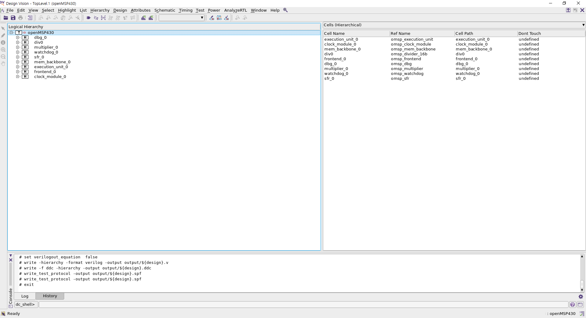
여기서 'Local Hierarchy' 탭에 있는 TOP 모듈인 openMSP430을 우클릭한 뒤, 'Schematic View'를 눌러 최종 회로를 확인할 수 있다. 완성된 회로를 더블클릭하면 세부 모듈까지 확인할 수 있다.

추후에 시간이 난다면 스크립트의 각 명령어가 어떤 역할을 하는지 하나하나씩 실행시켜 가며 기술할 예정이다.
3. 레이아웃 이전 기능성 검증(RTL vs 합성)
기능성 검증은 두 회로 간의 논리적 기능성이 일치하는지 확인하는 과정이다. 즉 A회로와 B회로가 논리적으로 똑같이 동작하는지 검증하는 과정으로, 만약 설계를 진행하기 전/후 회로가 논리적으로 똑같이 동작하지 않는다면 그 회로는 우리가 원하던 회로가 아니게 된다. 즉 아무 가치가 없는 회로가 되기 때문에 특정 설계 단계가 끝날 때마다 전/후 회로에 대해 기능성 검증을 진행할 필요가 있다. 기능성 검증을 진행하기 위해서는 기능성 검증 프로그램(이 글에서는 Synopsys의 Formality)과 검증 명령어 꾸러미인 스크립트가 필요하다.
기능성 검증 프로그램 설치과정은 2번의(2)를 참고할 수 있다. 검증 명령어 꾸러미인 스크립트의 경우 2번에서 언급한 링크의 자료를 다운받은 뒤, fm/scripts/fm_pre_script.tcl을 아래와 같이 변경한다.
set hdlin_dwroot "/d_drive/SYNOPSYS/syn/S-2021.06-SP4"

set_svf -append { ../syn/output/openMSP430_dc.svf }
set LIB_DIR "/home/zehonyi21/Desktop/MyDC/lib/SAED32_EDK/lib/stdcell_rvt/db_nldm"
read_db -container r $LIB_DIR/saed32rvt_tt1p05v25c.db
read_verilog -container r -libname WORK { ../rtl/openMSP430_defines.v
                      ../rtl/openMSP430.v
                      ../rtl/omsp_frontend.v
                      ../rtl/omsp_execution_unit.v
                      ../rtl/omsp_register_file.v
                      ../rtl/omsp_alu.v
                      ../rtl/omsp_sfr.v
                      ../rtl/omsp_clock_module.v
                      ../rtl/omsp_mem_backbone.v
                      ../rtl/omsp_watchdog.v
                      ../rtl/omsp_dbg.v
                      ../rtl/omsp_dbg_uart.v
                      ../rtl/omsp_dbg_hwbrk.v
                      ../rtl/omsp_multiplier.v
                       ../rtl/omsp_divider_16b.v
                      ../rtl/omsp_sync_reset.v
                      ../rtl/omsp_sync_cell.v
                      ../rtl/omsp_scan_mux.v
                      ../rtl/omsp_and_gate.v
                      ../rtl/omsp_wakeup_cell.v
                      ../rtl/omsp_clock_gate.v
                      ../rtl/omsp_clock_mux.v
}
set_top r:/WORK/openMSP430
read_db -container i $LIB_DIR/saed32rvt_tt1p05v25c.db
read_verilog -container i -libname WORK { ../syn/output/openMSP430_dc.v }
set_top i:/WORK/openMSP430

#set_constant -type port r:/WORK/Johnson_count/SE 0
#set_constant -type port i:/WORK/Johnson_count/SE 0

match


#set_dont_verify_point -type pin  r:/WORK/omsp_clock_module/U7/IN


#set_dont_verify_point -type port  i:/WORK/Johnson_count/SE

set_dont_verify {r:/WORK/openMSP430/sfr_0/wakeup_cell_nmi/wkup_out_reg }
set_dont_verify {r:/WORK/openMSP430/watchdog_0/wakeup_cell_wdog/wkup_out_reg }

verify

save_session -replace ../results/design_dc
위 스크립트를 통해 눈치챌 수 있듯이 hdlin_dwroot, 즉 DesignWare root 또는 디자인웨어 라이브러리의 경로로 "/d_drive/SYNOPSYS/syn/S-2021.06-SP4"를 사용하였으며 LIB_DIR 또는 라이브러리 경로로 "/home/zehonyi21/Desktop/MyDC/lib/SAED32_EDK/lib/stdcell_rvt/db_nldm"를 사용하였다.
이제 fm 폴더에서 Formality를 실행한 다음, 위 스크립트를 source해야 한다. 관련 명령어는 아래와 같다:
fm_gui
source ./scripts/fm_pre_script.tcl


여기서'Passing Points' 탭에 있는 DFF(Data Flip-Flop) 들을 더블클릭하면 레퍼런스 회로(여기서는 RTL)와 임플리멘테이션 회로(여기서는 합성)의 기능성을 비교할 수 있다.

추후에 시간이 난다면 스크립트의 각 명령어가 어떤 역할을 하는지 하나하나씩 실행시켜 가며 기술할 예정이다.
4. DFT 삽입
DFT(Design For Testability) 삽입이란 기존 설계에 Testability, 즉 시험가능성과 관련된 설계를 추가하는 과정이다. 이 과정을 통해 회로에 DFF의 작동여부를 테스트할 수 있는 Scan Chain을 생성할 수 있다. DFT 삽입을 진행하기 위해서는 DFT 삽입 프로그램(이 글에서는 Synopsys의 Design Compiler에 포함된 DFT Compiler)과 DFT 삽입 명령어 꾸러미인 스크립트가 필요하다.
DFT 삽입 프로그램 설치과정은 2번의(1)을 참고할 수 있다. 2번의 명령어 스크립트의 하단 주석을 통해 눈치챈 사람도 있겠지만 DFT 삽입 명령어 꾸러미인 스크립트는 합성 스크립트에 덧붙여서 수행된다.
2번에 있는 링크의 자료를 다운받은 뒤, syn/scripts/syn.tcl을 아래와 같이 변경한다.
gui_start

set design openMSP430
set_svf output/${design}_dc.svf
set_app_var hdlin_enable_hier_map true

set_app_var search_path "/home/zehonyi21/Desktop/MyDC/lib/SAED32_EDK/lib/stdcell_rvt/db_nldm"

set_app_var target_library "saed32rvt_tt1p05v25c.db"
set_app_var link_library "saed32rvt_tt1p05v25c.db"
# set_app_var symbol_library "../icons/saed90nm.sdb"
alias h history

sh rm -rf work
sh mkdir -p work
define_design_lib work -path ./work

echo "~~~Reading RTL~~~"
read_file -format verilog -top openMSP430 -autoread \
	{../rtl/openMSP430_defines.v
        ../rtl/openMSP430.v
        ../rtl/omsp_frontend.v
        ../rtl/omsp_execution_unit.v
        ../rtl/omsp_register_file.v
        ../rtl/omsp_alu.v
        ../rtl/omsp_sfr.v
        ../rtl/omsp_clock_module.v
        ../rtl/omsp_mem_backbone.v
        ../rtl/omsp_watchdog.v
        ../rtl/omsp_dbg.v
        ../rtl/omsp_dbg_uart.v
        ../rtl/omsp_dbg_i2c.v
        ../rtl/omsp_divider_16b.v
        ../rtl/omsp_dbg_hwbrk.v
        ../rtl/omsp_multiplier.v
        ../rtl/omsp_sync_reset.v
        ../rtl/omsp_sync_cell.v
        ../rtl/omsp_scan_mux.v
        ../rtl/omsp_and_gate.v
        ../rtl/omsp_wakeup_cell.v
        ../rtl/omsp_clock_gate.v
        ../rtl/omsp_clock_mux.v}

echo "~~~Analyzing RTL~~~"
analyze -library WORK -format verilog \
	{../rtl/openMSP430_defines.v
        ../rtl/openMSP430.v
        ../rtl/omsp_frontend.v
        ../rtl/omsp_execution_unit.v
        ../rtl/omsp_register_file.v
        ../rtl/omsp_alu.v
        ../rtl/omsp_sfr.v
        ../rtl/omsp_clock_module.v
        ../rtl/omsp_mem_backbone.v
        ../rtl/omsp_watchdog.v
        ../rtl/omsp_dbg.v
        ../rtl/omsp_dbg_uart.v
        ../rtl/omsp_dbg_i2c.v
        ../rtl/omsp_divider_16b.v
        ../rtl/omsp_dbg_hwbrk.v
        ../rtl/omsp_multiplier.v
        ../rtl/omsp_sync_reset.v
        ../rtl/omsp_sync_cell.v
        ../rtl/omsp_scan_mux.v
        ../rtl/omsp_and_gate.v
        ../rtl/omsp_wakeup_cell.v
        ../rtl/omsp_clock_gate.v
        ../rtl/omsp_clock_mux.v}

analyze -library work -format verilog ../rtl/${design}.v
elaborate $design -lib work
current_design
set_verification_top
uniquify

check_design
source ./cons/cons.tcl
link

# Prevent assignment statements in the Verilog netlist.
set_fix_multiple_port_nets -all -buffer_constants

# Configuration
# current_design $DESIGN_NAME
current_design $design
set_max_area  0.0
set_flatten false
set_structure true -timing true -boolean false

compile -map_effort medium

report_area > ./report/synth_area_dc.rpt
report_cell > ./report/synth_cells_dc.rpt
report_qor  > ./report/synth_qor_dc.rpt
report_resources > ./report/synth_resources_dc.rpt
report_timing -max_paths 10 > ./report/synth_timing_dc.rpt

write_sdc  output/${design}_dc.sdc

define_name_rules  no_case -case_insensitive
change_names -rule no_case -hierarchy
change_names -rule verilog -hierarchy
set verilogout_no_tri	 true
set verilogout_equation  false

write -hierarchy -format verilog -output output/${design}_dc.v
write -f ddc -hierarchy -output output/${design}_dc.ddc
set_svf -off

set_dft_signal -view spec         -type ScanEnable  -port scan_enable -active_state 1
set_dft_signal -view existing_dft -type ScanEnable  -port scan_enable -active_state 1
set_dft_signal -view spec         -type Constant    -port scan_mode   -active_state 1
set_dft_signal -view existing_dft -type Constant    -port scan_mode   -active_state 1
set_dft_signal -view existing_dft -type ScanClock   -port dco_clk     -timing [list 45 55]
set_dft_signal -view existing_dft -type ScanClock   -port lfxt_clk    -timing [list 45 55]
set_dft_signal -view existing_dft -type Reset       -port reset_n     -active 0

set_dft_insertion_configuration -preserve_design_name true
set_scan_configuration -style multiplexed_flip_flop
set_scan_configuration -clock_mixing mix_clocks
set_scan_configuration -chain_count 3
set_scan_element false [get_cells enable_latch_reg -hierarchical]
set_scan_element false [get_cells wkup_out_reg -hierarchical]
set_scan_element false [get_cells in0_select_s_reg -hierarchical]
set_scan_element false [get_cells *_disable_reg -hierarchical]
set_scan_element false clock_module_0/sync_cell_dco_wkup/data_sync_reg_0_

create_test_protocol

redirect -tee -file ./report/report.dft_drc           {dft_drc}
redirect -tee -file ./report/report.dft_drc           {dft_drc}
redirect      -file ./report/report.dft_drc_verbose   {dft_drc -verbose}
redirect      -file ./report/report.dft_drc_coverage  {dft_drc -coverage_estimate}
redirect      -file ./report/report.dft_scan_config   {report_scan_configuration}
redirect      -file ./report/report.dft_insert_config {report_dft_insertion_configuration}

dft_drc

redirect -tee -file ./report/report.dft_preview       {preview_dft}
redirect      -file ./report/report.dft_preview_all   {preview_dft -show all -test_points all}

insert_dft

compile   -scan -incremental

redirect      -file ./report/report.dft_drc_coverage  {dft_drc -coverage_estimate}

report_area > ./report/synth_area.rpt
report_cell > ./report/synth_cells.rpt
report_qor  > ./report/synth_qor.rpt
report_resources > ./report/synth_resources.rpt
report_timing -max_paths 10 > ./report/synth_timing.rpt

write_sdc  output/${design}.sdc
define_name_rules  no_case -case_insensitive
change_names -rule no_case -hierarchy
change_names -rule verilog -hierarchy
set verilogout_no_tri  true
set verilogout_equation  false

write -hierarchy -format verilog -output output/${design}.v
write -f ddc -hierarchy -output output/${design}.ddc
write_test_protocol -output output/${design}.spf
write_test_protocol -output output/${design}.spf


# exit
이제 Design Compiler를 실행한 다음, 위 스크립트를 source해야 한다. 관련 명령어가 담긴 쉘 스크립트는 아래와 같다:
rm -rf  log/* report/* output/*
mkdir -p log report output
dc_shell -f scripts/syn.tcl | tee log/syn.log
rm -rf  command.log filenames.log
이 스크립트를 syn 폴더에서 'run'으로 저장한 뒤 syn 폴더에서 실행한다. 명령어는 아래와 같다:
source ./run

텍스트 에디터를 통해 syn/output에 있는 openMSP430_dc.v와 openMSP430.v를 비교할 경우 test_si와 test_so가 추가된 모습을 확인할 수 있다.
추후에 시간이 난다면 스크립트의 각 명령어가 어떤 역할을 하는지 하나하나씩 실행시켜 가며 기술할 예정이다.
5. ATPG
ATPG(Automatic Test Pattern Generation)란 DFT 삽입이 끝난 디지털 회로의 입력 스티뮬러스, 즉 자극 값으로 자동 생성된 테스트 패턴, 즉 임의의 값들을 입력하여 회로가 잘 작동하는지 검증하는 일종의 DFT삽입 전용 테스트벤치 생성이다. 이 테스트벤치를 통해 stuck-at-0/stuck-at-1 fault와 같은 설계 결함을 미리 예방할 수 있다. ATPG를 진행하기 위해서는 ATPG 프로그램(이 글에서는 Synopsys의 TestMAX ATPG 및 TestMAX Diagnosis)과 ATPG 명령어 꾸러미인 스크립트가 필요하다.
ATPG 프로그램 설치과정은 2번의(6)을 참고할 수 있다. ATPG 명령어 꾸러미인 스크립트의 경우 2번에서 언급한 자료를 다운받은 뒤, syn/scripts/tmax.tcl 파일을 생성한 다음 아래의 내용을 입력한다.
#=============================================================================#
#                              Configuration                                  #
#=============================================================================#

set DESIGN_NAME      "openMSP430"

set SPF_FILE         "../syn/output/$DESIGN_NAME.spf"
set NETLIST_FILES    [list "../syn/output/$DESIGN_NAME.v"]

set LIB_DIR "/home/zehonyi21/Desktop/MyDC/lib/SAED32_EDK"
set LIBRARY_FILES    [list "$LIB_DIR/lib/stdcell_rvt/verilog/saed32nm.v"]


#=============================================================================#
#                           Read Design & Technology files                    #
#=============================================================================#

# Rules to be ignored
set_rules B7  ignore    ;# undriven module output pin
set_rules B8  ignore    ;# unconnected module input pin
set_rules B9  ignore    ;# undriven module internal net
set_rules B10 ignore    ;# unconnected module internal net
set_rules N20 ignore    ;# underspecified UDP
set_rules N21 ignore    ;# unsupported UDP entry
set_rules N23 ignore    ;# inconsistent UDP


# Reset TMAX
build -force
read_netlist -delete

# Read gate level netlist
foreach design_file $NETLIST_FILES {
    read_netlist $design_file
}

# Read library files
foreach lib_file $LIBRARY_FILES {
    read_netlist $lib_file
}

# Remove unused net connections
remove_net_connection -all

# Build the model
run_build_model $DESIGN_NAME


#=============================================================================#
#                                    Run DRC                                  #
#=============================================================================#

# Allow ATPG to use nonscan cell values loaded by the last shift.
set_drc -load_nonscan_cells

# Report settings
report_settings drc

# Run DRC
run_drc $SPF_FILE


#=============================================================================#
#                                      ATPG                                   #
#=============================================================================#

set_atpg -capture_cycles 4

set_faults -model stuck

set_atpg -abort_limit 10
report_settings atpg
report_settings simulation

run_atpg -auto

# Write the patterns
write_patterns output/$DESIGN_NAME.stil -format STIL -replace
# write_patterns output/$DESIGN_NAME.bin -replace
write_testbench -input output/$DESIGN_NAME.stil -output output/${DESIGN_NAME}_ATPG -replace

# Create report
redirect -file "./report/report.tmax_summary" {report_summaries}

# quit
위 스크립트를 통해 눈치챌 수 있듯이 LIB_DIR 또는 라이브러리 경로로 "/home/zehonyi21/Desktop/MyDC/lib/SAED32_EDK"를 사용하였다. 또 LIBRARY_FILES로 "$LIB_DIR/lib/stdcell_rvt/verilog/saed32nm.v"를 사용하였다는 사실을 확인할 수 있다. 합성이나 DFT 삽입 때와 달리 라이브러리 파일로 db파일이 아니라 v파일을 사용하였다.
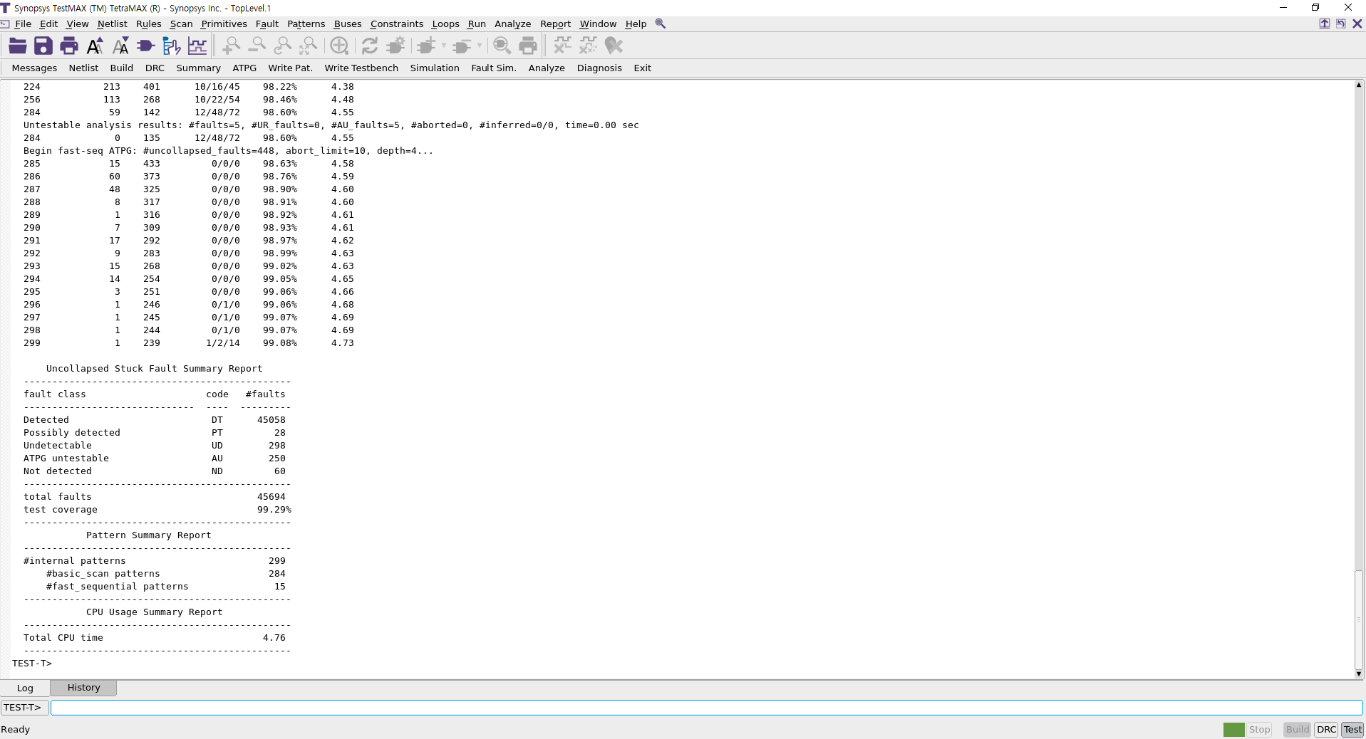
이제 syn 폴더에서 TestMAX & TetraMAX를 실행한 다음, 위 스크립트를 source해야 한다. 관련 명령어는 아래와 같다:
tmax_gui
source ./scripts/tmax.tcl

이제 주어진 패턴을 바탕으로 테스트벤치를 실행해볼 시간이다. syn/run_atpg 파일을 생성한 뒤, 아래 내용을 입력한다.
#!/bin/bash

#=============================================================================#
#                              Configuration                                  #
#=============================================================================#

design_name="openMSP430"
spf_file="../syn/output/$design_name.spf"
netlist_files="../syn/output/$design_name.v"
lib_dir="/home/zehonyi21/Desktop/MyDC/lib/SAED32_EDK"
library_files="$lib_dir/lib/stdcell_rvt/verilog/saed32nm.v"

#=============================================================================#
rm -rf csrc simv*
vargs="$vargs -full64 -debug_access+all -R +define+tmax_vcde"
vcs output/${design_name}_ATPG.v ../syn/output/$design_name.v \
    -v $lib_dir/lib/stdcell_rvt/verilog/saed32nm.v \
    -o simv_ATPG $vargs

# echo "Running ATPG simulation..."
# ./simv_ATPG
이후 아래 명령어를 입력하여 테스트벤치 시뮬레이션을 진행한다:
source ./run_atpg

시뮬레이션 결과 파형이 담긴 파일인 syn/output/openMSP430_ATPG.vcd을 GTKwave와 같은 파형 관찰 프로그램을 통해 불러올 경우 아래와 같은 파형을 얻을 수 있다.

추후에 시간이 난다면 스크립트의 각 명령어가 어떤 역할을 하는지 하나하나씩 실행시켜 가며 기술할 예정이다.
6. 레이아웃 설계
레이아웃은 DFT 삽입이 된 RTL을 바탕으로 셀의 위치, 전압 케이블 배선 등 물리적인 배치(Layout)를 설계하는 과정이다. 이 과정을 통해 RTL에 명시된 셀과 게이트들의 위치를 지정할 수 있으며 실제 파운드리(Foundry)에서 찍어낼 수 있는 도면 파일을 생성할 수 있다. 위에서 말했던 레고 조립 설명서의 비유에서 완성품을 실제 진열장에 전시할 때 어떤 위치에 놓아두어야 하며 지지대를 어떻게 거치시켜야 하는지 결정하는 과정이라고 생각할 수 있다. 레이아웃을 진행하기 위해서는 레이아웃 프로그램(이 글에서는 Synopsys의 ICC2 또는 Integrated Circuit Compiler 2)과 레이아웃 명령어 꾸러미인 스크립트가 필요하다.
레이아웃 프로그램 설치과정은 2번의(3)를 참고할 수 있다. 레이아웃 명령어 꾸러미인 스크립트의 경우 2번에서 언급한 링크의 자료를 다운받은 뒤, pnr/scripts/pnr.tcl을 아래와 같이 변경한다.
##############################################
########### 1. DESIGN SETUP ##################
##############################################

set design openMSP430

sh rm -rf $design

set sc_dir "/home/zehonyi21/Desktop/MyDC/lib/SAED32_EDK"
set run_dir "/home/zehonyi21/Desktop/SoC-Implementation-of-OpenMSP430-Microcontroller-main/pnr"

set_app_var search_path "/home/zehonyi21/Desktop/MyDC/lib/SAED32_EDK/lib/stdcell_rvt/db_nldm"

# set_app_var link_library "* saed32rvt_tt1p05v25c.db"
# set_app_var target_library "saed32rvt_tt1p05v25c.db"
# set_app_var synthetic_library "dw_foundation.sldb"
# set_app_var link_library [concat $link_library $synthetic_library]
set_app_var link_library  [list $search_path/saed32rvt_tt1p05v25c.db]

alias h history
alias rc "report_constraint -all_violators"

create_lib   ./${design} \
                -technology $sc_dir/tech/milkyway/saed32nm_1p9m_mw.tf \
		-ref_libs $sc_dir/lib/stdcell_rvt/lef/saed32nm_rvt_1p9m.lef

read_parasitic_tech -name nominal -tlup $sc_dir/tech/star_rcxt/saed32nm_1p9m_nominal.tluplus -layermap $sc_dir/tech/star_rcxt/saed32nm_tf_itf_tluplus.map
read_parasitic_tech -name tlupmax -tlup $sc_dir/tech/star_rcxt/saed32nm_1p9m_Cmax.tluplus -layermap $sc_dir/tech/star_rcxt/saed32nm_tf_itf_tluplus.map
read_parasitic_tech -name tlupmin -tlup $sc_dir/tech/star_rcxt/saed32nm_1p9m_Cmin.tluplus -layermap $sc_dir/tech/star_rcxt/saed32nm_tf_itf_tluplus.map


read_verilog -library ${design} -top ${design} $run_dir/syn_out/${design}.v
link_block

set_app_options -list {opt.timing.effort {medium}}
set_app_options -list {clock_opt.place.effort {high}}
set_app_options -list {place_opt.flow.clock_aware_placement {true}}
set_app_options -list {place_opt.final_place.effort {high}}
set_app_options -name place.coarse.continue_on_missing_scandef -value true
set_app_options -name mv.upf.use_preswitched_supply_for_macro_pins -value true

source  $run_dir/syn_out/${design}.sdc
set_propagated_clock [get_clocks dco_clk]
update_timing

save_lib -as ${design}_1_imported

##############################################
########### 2. Floorplan #####################
##############################################

## Create Starting Floorplan
############################
initialize_floorplan -core_utilization 0.33 \
	-flip_first_row true \
	-core_offset {20}
	# -side_length {300 300} -core_offset {20}

# source $run_dir/scripts/upf.tcl

place_pins -self

# Power domains TOP
create_power_domain TOP
#VDD
create_supply_port VDD
create_supply_net VDD -domain TOP
connect_supply_net VDD -ports VDD
#VSS
create_supply_port VSS
create_supply_net VSS -domain TOP
connect_supply_net VSS -ports VSS

set_domain_supply_net TOP -primary_power_net VDD -primary_ground_net VSS


# create_voltage_area -power_domains DIV -power VDD_DIV -ground VSS_DIV -nwell VDD_DIV -pwell VSS_DIV -name VA_DIV -region {{200.000 550.000} {850.000 800.000}} -cells [get_cells -physical_context -hierarchical \
# -regexp div0/.*]
# create_pg_region {pg_DIV} -voltage_area VA_DIV -expand {0 10}
# create_voltage_area -power_domains MULT -power VDD_MULT -ground VSS_MULT -nwell VDD_MULT -pwell VSS_MULT -name VA_MULT -region {{900.000 550.000} {1000.000 800.000}} -cells [get_cells -physical_context -hierarchical \
# -regexp multiplier_0/.*]
# create_pg_region {pg_MULT} -voltage_area VA_MULT -expand {0 10}

create_pg_region {pg_TOP} -voltage_area DEFAULT_VA

set_parasitic_parameters -early_spec tlupmax -early_temperature -40 -late_spec tlupmin -late_temperature 125
current_corner default
set_operating_conditions -max_library saed32rvt_tt1p05v25c -max tt1p05v25c -min_library saed32rvt_tt1p05v25c -min tt1p05v25c
current_corner default
set_voltage 1.050 -corner [current_corner] -object_list [get_supply_nets VDD]
set_voltage 0.00 -corner [current_corner] -object_list [get_supply_nets VSS]

add_port_state VSS -state {on 0.0}
# add_port_state VSS_DIV -state {on 0.0}
# add_port_state VSS_MULT -state {on 0.0}
add_port_state VDD -state {on 1.05}
# add_port_state VDD_DIV -state {on 1.05}
# add_port_state VDD_MULT -state {on 1.05}
create_pst ao_pst -supplies {VSS VDD}
add_pst_state ao -pst ao_pst -state {on on}

commit_upf

## CONSTRAINTS
##############
## Here, We define more constraints on your design that are related to floorplan stage.
report_ignored_layers
remove_ignored_layers -all
##set_ignored_layers -max_routing_layer metal6

## Initial Virtual Flat Placement
#################################
## Use the following command with any of its options to meet a specific target
#    create_fp_placement -timing -no_hierarchy_gravity -congestion
#     create_fp_placement

##AH## ## To show design-specific blocks
##AH## gui_set_highlight_options -current_color yellow
##AH## change_selection [get_cells   alu_unit/*]

##AH## gui_set_highlight_options -current_color blue
##AH## change_selection [get_cells   ALU_Control_unit/*]

##AH## gui_set_highlight_options -current_color green
##AH## change_selection [get_cells   datamem/*]

##AH## gui_set_highlight_options -current_color orange
##AH## change_selection [get_cells   reg_file/*]

## ASSESSMENT
#############
## Analyze Congestion
#route_fp_proto -congestion_map_only -effort medium
# View Congestion map : In GUI, Route > Global Route Congestion Map.

## Analyze Timing
#extract_rc; # Improves accuracy of timing after updated GR.

#report_timing -nosplit; # For Worst Setup violation report
#report_timing -nosplit -delay_type min; # For Worst Hold violation report

#report_constraint -all_violators -nosplit -max_delay; # For all Setup violation report
#report_constraint -all_violators -nosplit -min_delay; # For all Hold violations report

##Based on your assessment, you may need to do any of the following fixes

## FIXES
########
## You can use one or all of the follwoing based on your need.
#   set_fp_placement_strategy -virtual_IPO on
#
#   create_bounds -name "temp" -coordinate {55 0 270 270} datamem
#   create_bounds -name "temp1" -coordinate {0 0 104 270} reg_file
#
#   set_congestion_options -max_util 0.4 -coordinate {x1 y1 x2 y2}; # if cell density is causing congestion.
#
#   create_placement_blockage -name PB -type hard -bbox {x1 y1 x2 y2}
#
#   set_fp_placement_strategy -congestion_effort high
#
## Then you need to re-run create_fp_placement
#   create_fp_placement -incremental;
## Note:  use -incremental option if you want to refine the current virtual placement. Don't use it if you want to re-place the design from scratch

## If there still congestion, change ignored layers, if it is still there, increase floorplan area.

save_lib -as ${design}_2_fp


##################################################
########### 3. POWER NETWORK #####################
##################################################

## Defining Logical POWER/GROUND Connections
############################################
connect_pg_net -automatic

## Define Power Ring
####################
create_pg_ring_pattern ring_pattern \
	-horizontal_layer M9 \
	-horizontal_width {3} \
	-horizontal_spacing {1} \
	-vertical_layer M8 \
	-vertical_width {3} \
	-vertical_spacing {1}
set_pg_strategy core_ring \
	-pattern {{name:ring_pattern} {nets: {VDD VSS}}{offset: {1 1}}} \
	-core

## Define Power Mesh
####################

create_pg_mesh_pattern mesh_pattern \
	-parameters {w1 w2 f} \
	-layers { \
		{{horizontal_layer: M7}{width: @w1} \
			{spacing: minimum}{pitch: 7} {offset: @f}} \
		{{vertical_layer: M6}{width: @w2} \
			{spacing: minimum}{pitch: 7} {offset: @f}}}
# create_pg_mesh_pattern strap_pattern \
# 	-layers {{vertical_layer : M6} {width : 1} {spacing : minimum} {pitch : 25} {trim : false}}
set_pg_strategy mesh \
	-core \
	-pattern {{name: mesh_pattern} {nets: VDD VSS} \
				{parameters: {2 2 1}}} \
	-extension {{{stop : outermost_ring}}}

## Define Power rails
####################
create_pg_std_cell_conn_pattern rail_pattern \
	-layers M5
set_pg_strategy M5_rails \
	-core \
	-pattern {{name: rail_pattern} {nets: VDD VSS}} \
	-extension {{{stop : outermost_ring}}}

compile_pg -strategies {core_ring mesh M5_rails}

save_lib -as ${design}_3_power

##############################################
########### 4. Placement #####################
##############################################
puts "start_place"

## CHECKS
#########
report_ignored_layers ; # To Make sure they are as wanted.
check_design -checks pre_placement_stage
check_physical_constraints

## CONSTRAINTS
##############
## Here, We define more constraints on your design that are related to placement stage.

#### Scenario Creation ####create_scenario pw
#### Scenario Creation ####set_operating_conditions worst_low
#### Scenario Creation ####set_tlu_plus_files -max_tluplus $tlupmax \
#### Scenario Creation ####                   -min_tluplus $tlupmin \
#### Scenario Creation ####     		   -tech2itf_map $tech2itf
#### Scenario Creation ####
#### Scenario Creation ####set_scenario_options -leakage_power true; #If we need to optimize leakage power, more effective for multi-Vth designs.
#### Scenario Creation ####set power_default_toggle_rate 0.003
#### Scenario Creation ####set_scenario_options -dynamic_power true
#### Scenario Creation ####
#### Scenario Creation ####source  ../syn/cons/cons.tcl
#### Scenario Creation ####set_propagated_clock [get_clocks clk]
#### Scenario Creation ####
#### Scenario Creation ####set_optimize_pre_cts_power_options -low_power_placement true
#### Scenario Creation ####
#### Scenario Creation ####report_scenario_options


## INITIAL PLACEMENT
####################
## Initial Placement can be done using the following command using any of its target options
create_placement
legalize_placement -cells [get_cells *]

#place_opt -area_recovery |-power |-congestion|
place_opt

## ASSESSMENT
#############
## Open Congestion Map. == > If congested, improve congestion similar to floorplanning.
## Report Timing

## FIXES
########
# For seriuos congestion issue use the following commands:
#   set placer_enable_enhanced_router TRUE; # enabling the actual GR instead of GR estimator. Increased run time!
#   refine_placement ==> Optimizes congestion only

# If there are violating timing paths, apply optimization -focus- as needed:
#   report_path_group
#   group_path -name clk -critical_range 1 -weight 5


#The  psynopt  command  performs incremental preroute or postroute opti-
#mization on the current design. Performs incremental timing-driven  (setup timing, by default) logic optimization with placement legalization.
# It considers other targets using different options
# ex : psynopt -no_design_rule | -only_design_rule | -size_only ==> Used for Focused placment optimization

## FINAL ASSESSMENT
###################

check_legality
## If no legalized cells => legalize_placement -effort high -incremental
# Check Congestion
# Check Timing
# report_design_physical -utilization

# DEFINING POWER/GROUND NETS AND PINS
connect_pg_net -automatic

## Tie fixed values
set tie_pins [get_pins -all -filter "constant_value == 0 || constant_value == 0 && name !~ V* && is_hierarchical == false "]

connect_pg_net -automatic

puts "finish_place"

save_lib -as ${design}_4_placed

##############################################
########### 5. CTS       #####################
##############################################

puts "start_cts"

## CHECKS
#########
check_design -checks pre_clock_tree_stage
check_clock_trees -clocks dco_clk


## CONSTRAINTS
##############
## Here, We define more constraints on your design that are related to CTS stage.

# set_driving_cell -lib_cell IBUFFX16* -pin ZN [get_ports dco_clk]
###OR
set_input_transition -rise 0.3 [get_ports dco_clk]
set_input_transition -fall 0.2 [get_ports dco_clk]


#### Set Clock Exceptions


### Set Clock Control/Targets
set_clock_tree_options \
	-clocks dco_clk \
	-target_latency 0.1 \
	-target_skew 0.5
        #         -clock_trees dco_clk \
		# -target_early_delay 0.1 \
		# -target_skew 0.5 \
		# -max_capacitance 300 \
		# -max_fanout 10 \
		# -max_transition 0.3

# set_clock_tree_options -clock_trees dco_clk \
# 		-buffer_relocation true \
# 		-buffer_sizing true \
# 		-gate_relocation true \
# 		-gate_sizing true
set_clock_tree_options \
	-clocks lfxt_clk \
	-target_latency 0.1 \
	-target_skew 0.5
        #         -clock_trees lfxt_clk \
		# -target_early_delay 0.1 \
		# -target_skew 0.5 \
		# -max_capacitance 300 \
		# -max_fanout 10 \
		# -max_transition 0.3

# set_clock_tree_options -clock_trees lfxt_clk \
# 		-buffer_relocation true \
# 		-buffer_sizing true \
# 		-gate_relocation true \
# 		-gate_sizing true

## Selection of CTS cells
set_clock_tree_reference_subset -clocks dco_clk -lib_cells [get_lib_cells */IBUFFX*]
set_clock_tree_reference_subset -clocks lfxt_clk -lib_cells [get_lib_cells */IBUFFX*]
#set_clock_tree_references -references [get_lib_cells */BUF*]
#set_clock_tree_references -references [get_lib_cells */INV*]

## Selection of CTO cells
#set_clock_tree_references -sizing_only -references "BEST_PRACTICE_buffers_for_CTS_CTO_sizing"
#set_clock_tree_references -delay_insertion_only -references "BEST_PRACTICE_cels_for_CTS_CTO_delay_insertion"


### Set Clock Physical Constraints
## Clock Non-Default Ruls (NDR) - Set it to be double width and double spacing
# create_routing_rule my_route_rule  \
#   -widths   {M3 0.14 M4 0.28 M5 0.28} \
#   -spacings {M3 0.14 M4 0.28 M5 0.28}

# set_clock_tree_options -clock_trees clk \
#                        -routing_rule my_route_rule  \
# 		       -layer_list "M3 M4 M5"

# set_routing_rule {dco_clk lfxt_clk} -rule my_route_rule

## To avoid NDR at clock sinks
# set_clock_tree_options -use_default_routing_for_sinks 1

report_clock_tree_options

## Clock Tree : Synhtesis, Optimization, and Routing
####################################################
## The 3 steps can be done with the combo command clock_opt. But below, we do them individually.

## 1- CTS
synthesize_clock_trees -clocks dco_clk
clock_opt
## analyze
report_utilization
report_clock_qor -largest 5 -smallest 5
report_timing
report_constraints -all_violators -max_delay -min_delay


    # report_design_physical -utilization
    # report_clock_tree -summary ; # reports for the clock tree, regardless of relation between FFs
    # report_clock_tree
    # report_clock_timing -type summary ; # reports for the clock tree, considering relation between FFs
    # report_timing
    # report_timing -delay_type min
    # report_constraints -all_violators -max_delay -min_delay
    # Check Congestion
    # Check Timing


## 2- CTO
## To Consider Hold Fix -- Design Dependent
# set_fix_hold [all_clocks]
#   set_fix_hold_options -prioritize_tns
# clock_opt -only_psyn -no_clock_route
#analyze


## 3- Clock Tree Routing
route_group -all_clock_nets
#analyze


## If any issue at analysis, update CT constraints
##################################################

# DEFINING POWER/GROUND NETS AND PINS
connect_pg_net -automatic

save_lib -as ${design}_5_cts

puts "finish_cts"

##############################################
########### 6. Routing   #####################
##############################################

## lists all library cells used in the design
report_lib_cells -objects [get_lib_cells -of_objects saed32rvt_tt1p05v25c]
## Before starting to route, you should add spare cells
add_spare_cells -lib_cell {NOR2X4_RVT NAND2X4_RVT} \
		   -num_instances 20 \
		   -cell_name SPARE_PREFIX_NAME \
		   -input_pin_connect_type tie_low

# set_dont_touch  [get_cells SPARE_PREFIX_NAME*] true
# set_attribute [get_cells SPARE_PREFIX_NAME*]  is_soft_fixed true
legalize_placement -cells [get_cells SPARE_PREFIX_NAME*]


##############################################

puts "start_route"

check_design -checks pre_route_stage
report_ideal_network
all_high_transitive_fanout -nets -threshold 100
check_routability

get_lib_timing_arcs -of_objects saed32rvt_tt1p05v25c/*/*
#Defines the delay model used to compute a timing arc delay value for a cell or net
#set_delay_calculation_options -preroute     elmore | awe (Asymptotic Waveform Evaluation)
#                              -routed_clock elmore | arnoldi
#			       -postroute    elmore | arnoldi
#			       -awe_effort     low | medium | high
#			       -arnoldi_effort low | medium | high


# set_route_options -groute_timing_driven true \
# 	          -groute_incremental true \
# 	          -track_assign_timing_driven true \
# 	          -same_net_notch check_and_fix

# set_si_options -route_xtalk_prevention true\
# 	       -delta_delay true \
# 	       -min_delta_delay true \
# 	       -static_noise true\
# 	       -timing_window true


## route_opt : global, track, and detail routing, S&R, logic and placement optimizations with ECO routing
##             End goal: Design that meets timing, crosstalk and route DRC rules

#route_opt -effort high \
#	  -stage track        : which stage to run optimization after
#	  -xtalk_reduction    : to reduce crosstalk in routing
#	  -incremental        : to improve results of a routed design.
#	  -initial_route_only : This is to avoid full routing and post-routing optimizations. Only do the basic steps.

## To Consider Hold Fix
#   set_fix_hold_options -prioritize_tns
#    set_fix_hold [all_clocks]
#    set_prefer -min  [get_lib_cells "*/BUF_X2 */BUF_X1"]
#    set_fix_hold_options -preferred_buffer

route_auto
# route_opt
# psynopt  -only_hold_time -congestion
route_eco -open_net_driven true

check_routes
route_detail -incremental true -initial_drc_from_input true

add_redundant_vias
check_routes
route_detail -incremental true -initial_drc_from_input true

connect_pg_net -automatic


#report_noise
#report_timing -crosstalk_delta


save_lib -as ${design}_6_routed

puts "finish_route"

##############################################
########### 7. Finishing #####################
##############################################


create_stdcell_fillers -lib_cells {SHFILL128_RVT SHFILL64_RVT SHFILL3_RVT SHFILL2_RVT SHFILL1_RVT}


connect_pg_net -automatic

check_legality

route_eco
save_lib -as ${design}_7_finished

save_lib -as ${design}

##############################################
########### 8. Checks and Outputs ############
##############################################

check_routes
check_lvs -checks {short open}

write_gds -layer_map $sc_dir/tech/milkyway/saed32nm_1p9m_gdsout_mw.map \
		  -fill include \
		  -child_depth 20 \
		  -output_pin all \
		  -lib_cell_view frame \
		  -library $design \
		  ./output/${design}.gds

define_name_rules  no_case -case_insensitive
change_names -rule no_case -hierarchy
change_names -rule verilog -hierarchy
set verilogout_no_tri	 true
set verilogout_equation  false


write_verilog -include {pg_objects} ./output/${design}_icc.v

write_verilog ./output/${design}_icc_nopg.v

update_timing -full
write_parasitics -output {./output/mips_16.spef}


# close_lib -all -save_designs

# exit
이때 ' 4. DFT 삽입 ' 결과물들 중 하나인 syn/output/openMSP430.sdc를 pnr/syn_out/에 옮겨놓아야 sdc파일을 인식할 수 있다. 위 스크립트에서 눈치챈 사람들도 있겠지만 라이브러리는 SAED32, 즉 SYNOPSYS ARMENIA Educational Department의 32/28nm 1P9M 1.05v/1.8v/2.5v 공정을 사용하였으며 라이브러리 경로, 즉 search_path로 "/home/zehonyi21/Desktop/MyDC/lib/SAED32_EDK/lib/stdcell_rvt/db_nldm"를 사용하였다는 사실을 확인할 수 있다.
이제 pnr 폴더에서 ICC2를 실행한 다음, 위 스크립트를 source해야 한다. 관련 명령어는 아래와 같다:
icc2_gui
source ./scripts/pnr.tcl
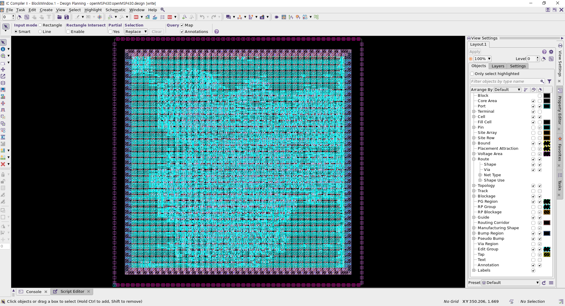
추후에 시간이 난다면 스크립트의 각 명령어가 어떤 역할을 하는지 하나하나씩 실행시켜 가며 기술할 예정이다.
7. 레이아웃 이후 기능성 검증(DFT 삽입 vs 레이아웃)
기능성 검증은 두 회로 간의 논리적 기능성이 일치하는지 확인하는 과정이다. 즉 A회로와 B회로가 논리적으로 똑같이 동작하는지 검증하는 과정으로, 만약 설계를 진행하기 전/후 회로가 논리적으로 똑같이 동작하지 않는다면 그 회로는 우리가 원하던 회로가 아니게 된다. 즉 아무 가치가 없는 회로가 되기 때문에 특정 설계 단계가 끝날 때마다 전/후 회로에 대해 기능성 검증을 진행할 필요가 있다. 기능성 검증을 진행하기 위해서는 기능성 검증 프로그램(이 글에서는 Synopsys의 Formality)과 검증 명령어 꾸러미인 스크립트가 필요하다.
기능성 검증 프로그램 설치과정은 2번의(2)를 참고할 수 있다. 검증 명령어 꾸러미인 스크립트의 경우 2번에서 언급한 링크의 자료를 다운받은 뒤, fm/Post-layout/scripts/fm_post_script.tcl을 아래와 같이 변경한다.
set hdlin_error_on_supply_type_port false

set LIB_DIR "/home/zehonyi21/Desktop/MyDC/lib/SAED32_EDK/lib/stdcell_rvt/db_nldm"
read_db -container r $LIB_DIR/saed32rvt_tt1p05v25c.db
read_verilog -container r -libname WORK -01 { ../syn/output/openMSP430.v }
set_top r:/WORK/openMSP430
read_db -container i $LIB_DIR/saed32rvt_tt1p05v25c.db
read_verilog -container i -libname WORK -01 { ../pnr/output/openMSP430_icc_nopg.v }
set_top i:/WORK/openMSP430

match

verify

save_session -replace {../results/design_icc}
위 스크립트를 통해 눈치챌 수 있듯이 LIB_DIR 또는 라이브러리 경로로 "/home/zehonyi21/Desktop/MyDC/lib/SAED32_EDK/lib/stdcell_rvt/db_nldm"를 사용하였다.
이제 fm 폴더에서 Formality를 실행한 다음, 위 스크립트를 source해야 한다. 관련 명령어는 아래와 같다:
fm_gui
source ./Post-layout/scripts/fm_post_script.tcl

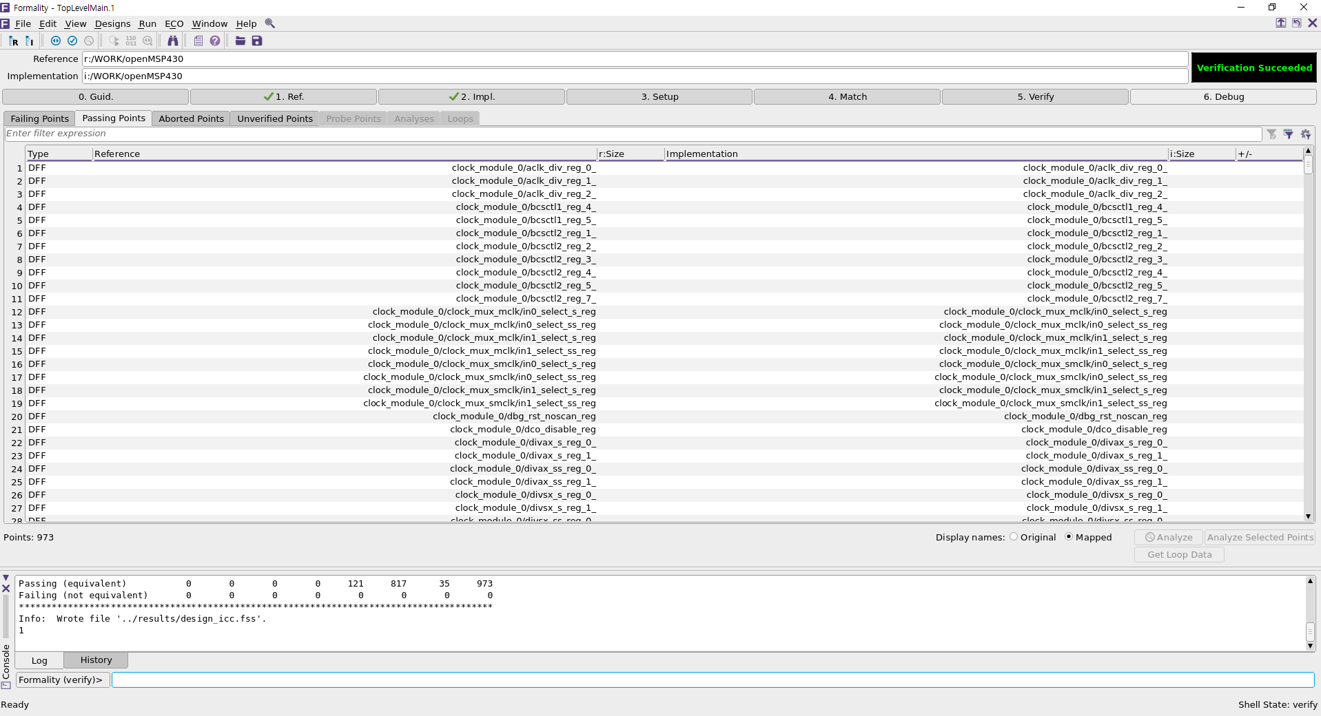
여기서'Passing Points' 탭에 있는 DFF(Data Flip-Flop) 들을 더블클릭하면 레퍼런스 회로(여기서는 DFT 삽입)와 임플리멘테이션 회로(여기서는 레이아웃)의 기능성을 비교할 수 있다.
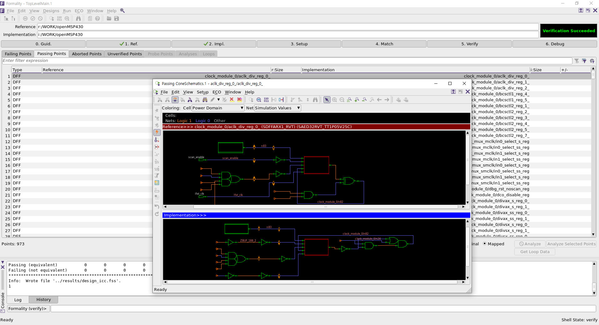
추후에 시간이 난다면 스크립트의 각 명령어가 어떤 역할을 하는지 하나하나씩 실행시켜 가며 기술할 예정이다.
III. 결론
오늘 우리는 Synopsys VLSI CAD Tool을 설치한 뒤, 디지털 집적회로를 설계할 수 있었다. 그러나 우리는 STA(Static Timing Analysis)를 포함한 모든 과정이 완벽하게 포함된 디지털 집적회로를 바로 설계할 수는 없었다. 그럼에도 이 글을 작성해서 후대에 남겨준다면, 이 글은 디지털 회로설계를 배우고 싶어 하는 후배들에게 북극성(Polaris)과 시리우스(Sirius)처럼 칠흑 같은 어둠을 밝히는 횃불이 될 것이다. 누군가는 디지털 회로설계 분야가 컴퓨터공학 느낌이 난다거나 건축 및 예술 관련 학과 느낌이 난다고 생각할 수 있다. 어느 정도 일리 있는 말이다. 디지털 회로설계자는 전자공학 및 컴퓨터과학(공학)을 기반으로 삼는 공학자이며 동시에 건축/예술가이기도 하다. 부족한 글이지만 디지털 회로 설계할 때 참고가 되었으면 좋겠다.
IV. 도움이 될 만한 링크
OpenLane
(https://github.com/The-OpenROAD-Project/OpenLane)
LibreLane
(https://github.com/librelane/librelane)
Simple DC Compiler Project
(https://github.com/parthpower/DCC_Basic)
후기
닌텐도와 컴퓨터는 너무 재미있다. 그러나 '신선놀음에 도끼자루 썩는 줄 모른다' 라는 말이 있듯이 필자는 닌텐도와 컴퓨터에 빠져 방황하는 삶을 살았다. 그 결과 시간은 쏜살같이 지나갔고, 돌이켜봤을 때 내 인생은 닌텐도와 컴퓨터를 제외하고는 아무것도 남지 않았다. 신이 있다면 부디 제 인생을 보살펴주시어 앞으로 제가 잘못된 길로 빠지지 않도록 도와주시길 간청한다.
Artist: Valve - Mike Morasky - Aperture Science Psychoacoustics Laboratory
Album: Portal 2 Soundtrack Volume 3 - Songs to Test By
Track: 12
Title: Cara Mia Addio
(https://www.thinkwithportals.com/music.php)
(https://www.youtube.com/watch?v=kis6V6qwYxI)